background image

15

Isis

®

WWW.BIGASSFANS.COM     ©2011 DELTA T CORP.     DBA BIG ASS FAN CO.     ALL RIGHTS RESERVED

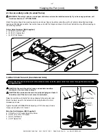
Mounting Method: Wood Frame Mounting (cont.)

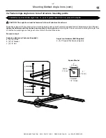
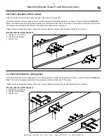
2b. Fasten brackets (to floor joists)

Note: This method should be used when the tops of the joists are inaccessible.

Fasten the brackets to the mounting points on the floor joists with the Mounting Hardware as shown. Torque the bolts to 

25 ft·lb


(33.9 

N·m)

The brackets should be facing inward and be mounted flush with the tops of the joists or in the centers of the joists. 

Note: Ensure 

the brackets are positioned so the fan will not interfere if the ceiling section is replaced. 

Using a level and carpenter’s square, ensure the mounting brackets are level and the opposing holes are concentric.

Mounting Hardware (BAF-Supplied):

a.  (8) 5/16”-18 x 2-1/2” Bolt

b.  (16) 5/16” Flat Washer

c.  (8) 5/16” Nut

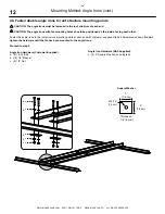
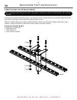
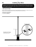
2c. Fasten brackets (to ceiling joists)

Fasten the brackets to the mounting points on the ceiling joists with the Mounting Hardware as shown. Torque the bolts to 

25 ft·lb (33.9 

N·m)

. The tops of the brackets should be facing outward and flush with the tops of the beams.

Using a level and carpenter’s square, ensure the mounting brackets are level and the opposing holes are concentric.

Mounting Hardware (BAF-Supplied):

a.  (8) 5/16”-18 x 2-1/2” Bolt

b.  (16) 5/16” Flat Washer

c.  (8) 5/16” Nut

a

b

c

c

b

b

a

b

Summary of Contents for Isis

Page 1: ...INSTALLATION GUIDE For help call 1 877 BIG FANS or visit www BigAssFans com ...

Page 2: ...the winglets or airfoil tips must be at a distance that is at least 2x the measure of the fan s diameter Will the fan be mounted where it will not come into direct contact with water The fan should not be mounted where it will come into direct contact with water unless it is labeled Suitable for use in wet locations Will the distance between multiple fans be at least 2 5x the fans diameter when me...

Page 3: ...tates All other trademarks used herein are the properties of their respective owners The information contained in this document is subject to change without notice For the most up to date information see the online Isis Installation Guide at www bigassfans com May be covered by one or more of the following United States Patents 6244821 6589016 6817835 6939108 7252478 7284960 D607988 D587799 765479...

Page 4: ...tallation of this fan WARNING To reduce the risk of fire electric shock and injury to persons Big Ass Fans must be installed with Big Ass Fan supplied controllers that are marked on their cartons to indicate the suitability with this model Other parts cannot be substituted CAUTION When service or replacement of a component in the fan requires the removal or disconnection of a safety device the saf...

Page 5: ...lation See Installing Airfoils on page 23 Winglet installation See Installing Airfoils on page 23 Wiring the controller and fan See Electrical Installation on page 25 Mounting the controller See Mounting the Wall Controller on page 28 Operating the fan See Fan Operation on page 29 Hanging the fan See Hanging the Fan on page 18 Isis WWW BIGASSFANS COM 2011 DELTA T CORP DBA BIG ASS FAN CO ALL RIGHTS...

Page 6: ...ptional mounting kits see the Optional Parts Order Form p 37 I Beam Z Purlins Solid Beam See complete instructions included with the Z Purlin Installation Kit See complete instructions included with the L Bracket Installation Kit See complete instructions included with the I Beam Adapter Installation Kit Angle Irons See page 9 for mounting instructions Isis WWW BIGASSFANS COM 2011 DELTA T CORP DBA...

Page 7: ...o Floor Joists 15 2c Fasten Brackets to Ceiling Joists 15 3 Attach Mount to Wood Framing Channels 16 4 Fasten Wood Framing Channels to Brackets 17 Hanging the Fan 1 Attach Extension Tube to Upper Mount 18 2a Secure Safety Cable to Angle Irons 18 2b Secure Safety Cable to Safety Clips 18 2c Secure Safety Cable to Wood Frame 19 3 Attach Main Fan Unit to Extension Tube 19 Installing Guy Wires 1 Attac...

Page 8: ...eventive Maintenance 33 Troubleshooting General Troubleshooting 34 Electrical Troubleshooting 34 Annual Maintenance Checklist Annual Maintenance Checklist 35 Optional Parts Order Form Optional Parts Order Form 37 Limited Warranty Warranty Policy 39 Acknowledgment Return Instructions 43 Warranty Claim Form 45 Responsibility Agreement 46 Big Ass Fan Certified Installers Check In Procedure 47 Close O...

Page 9: ...sign of our fans combines the best of both form and function to bring power performance and a sleek look to any setting More importantly you have purchased a product that is backed by extensive research thorough testing and quality manufacturing We re ready to answer any questions or comments at 1 877 BIG FANS or visit our Web site at www bigassfans com Who we are and what we do Big Ass Fans has b...

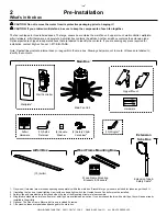
Page 10: ... labeled to identify the contents Main Box1 Hardware Upper Mount Main Fan Unit Wall Controller Wallplate2 Extension Tube Box Extension Tube Safety Cable6 Airfoil Box 10 Airfoil 1 Guy wires if ordered are marked and packaged separately within the main box Brackets for guy wires are included for tubes longer than 4 ft 2 If installing the fan on a typical lighting circuit with one basic light switch ...

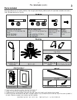
Page 11: ...alized installation instructions Note Drawings below are not to scale Upper Mount Extension Tube Safety Cable1 Main Fan Unit Wood Frame Mounting Brackets2 Wood Framing Channels2 1 The safety cable is attached to extension tube with a 3 8 bolt and nut 2 Optional The Wood Frame Mounting kit is only included if ordered 3 If installing the fan on a typical lighting circuit with one basic light switch ...

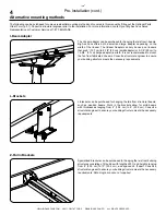
Page 12: ...25 cm to 14 5 8 37 cm large adapter in width It is not recommended to mount the fan from fabricated I beams Consult a structural engineer to ensure your building structure meets the necessary requirements I Beam Adapter L Brackets L brackets can be purchased for hanging the Isis from structural beams such as wooden beams Slots in the brackets allow for solid beams with thicknesses ranging from 4 1...

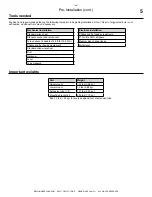
Page 13: ...ginning installation Note This list of suggested tools is not exhaustive Additional tools may be necessary Mechanical installation Standard wrench set Standard socket and ratchet set Torque wrench capable of 25 ft lb 33 9 N m Phillips and flat head screwdrivers Standard allen wrench set Drill Hacksaw Level Tape measure Electrical installation Phillips and flat head screwdrivers 10 to 14AWG strippe...

Page 14: ...per mount Secures the fan to the mounting structure B Extension tube Extends the fan from the ceiling and provides a path for wiring C Main fan unit Includes motor hub lower mount and power wire D Airfoil Provides air movement The unique patented design provides efficient and effective air movement E Winglet Improves efficiency of the fan Winglets are standard on Isis fans however airfoil tips are...

Page 15: ...h water unless the fan is labeled Suitable for use in wet locations Adhere to the safety requirements in the table below when selecting where to mount the fan Safety requirement Minimum distances Clearance 2 ft from all fan parts The fan installation area must be free of obstructions such as lights cables sprinklers or other building structure Blade height 10 ft above the floor HVAC equipment 1x f...

Page 16: ...Notes ...

Page 17: ... the fan and its method of attachment A structural engineer should verify that the mounting structure is adequate prior to fan installation Verifying the stability of the mounting structure is the sole responsibility of the customer and or end user and Big Ass Fans hereby expressly disclaims any liability arising therefrom or arising from the use of any materials or hardware other than those suppl...

Page 18: ...n the angle irons to each other and tighten the bolts to 25 ft lb 33 9 N m using a 3 4 socket with torque wrench Repeat step for remaining two angle irons Proceed to step 4b Angle Iron Hardware Customer Supplied a 2 1 2 13 Bolt b 4 1 2 Washer c 2 1 2 Nut Side View a b b c 2 Pre drill angle irons Drill two Ø 9 16 1 4 cm holes exactly 5 1 2 14 cm apart in the centers of two angle irons Measure the d...

Page 19: ...e mounting points at each end with customer supplied Grade 8 hardware as shown Do not tighten the hardware until the fan has been mounted to the angle irons Note Big Ass Fans recommends orienting the angle irons so that the horizontal legs are facing each other Refer to the illustration below Proceed to step 5 Angle Iron Hardware Customer Supplied a 4 1 2 13 Bolt b 8 1 2 Washer c 4 1 2 Nut 3 7 6 c...

Page 20: ...inside facing each other Fasten the angle irons to the roof structure mounting points at each end with customer supplied Grade 8 hardware as shown Do not tighten the hardware until the fan has been mounted to the angle irons Proceed to step 5 Angle Iron Hardware Customer Supplied a 8 1 2 13 Bolt b 16 1 2 Washer c 8 1 2 Nut A 3 7 6 cm 3 7 6 cm Ø 9 16 1 4 cm Thickness 1 4 6 mm Square Washer b a d b ...

Page 21: ...ith the Mounting Hardware as shown Consult the diagrams below for distances between the angle irons Torque the bolts to 25 ft lb 33 9 N m using a torque wrench with a 9 16 socket Note If desired the upper mount and extension tube can be pre assembled DO NOT tighten the bolts until the fan is installed and hanging freely to allow for balancing Mounting Hardware BAF Supplied a 4 3 8 16 x 1 1 2 GR 8 ...

Page 22: ...ler s responsibility to verify the safe performance of the fan when operated in the intended environment CAUTION Do not install the fan from a single beam or a conduit box CAUTION Ensure the mounting location will not expose the fan to direct contact with water unless the fan is labeled Suitable for use in wet locations 1 Identify mounting location Locate the area on the beams from which the fan w...

Page 23: ... will not interfere if the ceiling section is replaced Using a level and carpenter s square ensure the mounting brackets are level and the opposing holes are concentric Mounting Hardware BAF Supplied a 8 5 16 18 x 2 1 2 Bolt b 16 5 16 Flat Washer c 8 5 16 Nut 2c Fasten brackets to ceiling joists Fasten the brackets to the mounting points on the ceiling joists with the Mounting Hardware as shown To...

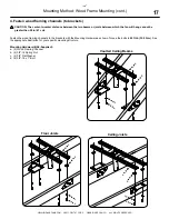
Page 24: ...ing channels using the Mounting Hardware as shown Measure the distance between the mounting brackets bolt head to bolt head so that the wood framing channels have enough clearance in between the brackets Cut both wood framing channels to the measured length Mounting Hardware BAF Supplied a 4 3 8 16 x 1 1 2 GR 8 Bolt b 8 3 8 Flat Washer c 4 3 8 Nylock Nut d 2 Wood Framing Channel a b b c d When cut...

Page 25: ...n which the fan will hang cannot be greater than 24 in 61 cm Fasten the wood framing channels to the brackets with the Mounting Hardware as shown Torque the bolts to 25 ft lb 33 9 N m See the appropriate illustration for your specific mounting structure Mounting Hardware BAF Supplied a 2 Wood Framing Channel b 4 3 8 16 Spring Nut c 4 3 8 Flat Washer d 4 3 8 16 x 1 Bolt Vaulted Ceiling Beams Ceilin...

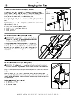
Page 26: ...l Customer Service at 1 877 BIG FANS Secure the safety cable to the mounting structure by wrapping it around the structure and securing the loose ends with the Gripple as shown The cable must be drawn tightly around the structure leaving as little slack as possible with the Gripple tucked inside the extension tube Note Exact mounting installation may differ from the illustration a b b c Safety Cab...

Page 27: ...1 2 Socket Head Cap Screw b 1 3 8 x 3 4 OD x 1 2 Spacer c 2 3 8 Flat Washer d 1 3 8 Nylock Nut Before attaching the main fan unit to the extension tube route the power cable from motor through the extension tube and upper mount Hanging the Fan cont Power Cable a c d c Lower Mount 2c Secure safety cable to wood frame WARNING The safety cable is a crucial part of the fan and must be installed correc...

Page 28: ...lock Flange Nut Guy Wire Clamps a b 4 ft Ensure the guy wire clamps are no higher than 4 ft 1 2 m above the top of the main fan unit Guy wires may not be included in your fan order They are intended to restrain the fan s lateral movement and are only included in fan orders that have extension tubes 4 ft 1 2 m or longer Depending on the operational environment wind mounting structure etc guy wires ...

Page 29: ...ordingly Fasten the small eyebolt and nut onto the beam clamp the nut will be on the outside of the beam clamp Loop the guy wire through its crimped end to secure it to the eyebolt as shown Guy Wire Hardware BAF Supplied a 1 4 Beam Clamp b 1 4 20 x 1 Eyebolt c 1 4 20 Hex Nut d Guy Wire a d b c 3b Attach eyebolt wood frame mounting The guy wire should be at approximately a 45 angle from the extensi...

Page 30: ...le 5 Install three remaining guy wires CAUTION The guy wires should be spaced evenly around the fan CAUTION Over tightening the guy wires could throw the fan off balance Repeat steps 3 4 to install the three remaining guy wires Evenly cinch all four guy wires into place using the Gripples The guy wires should be taut evenly spaced around the fan and away from the path of the airfoils Maintain a di...

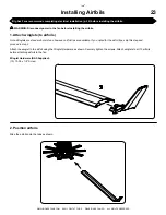
Page 31: ...WARNING Disconnect power to the fan before installing the airfoils 1 Attach winglets to airfoils Note Winglets are standard on Isis fans however airfoil tips are available If you opted for the airfoil tips skip this step and proceed to step 2 Attach the winglet to the airfoil using the Winglet Hardware as shown Securely tighten the screws Attach winglets to all 10 airfoils before attaching airfoil...

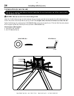
Page 32: ...ot tighten bolts until all airfoil retainers have been attached Tighten the bolts along the outside perimeter to 29 ft lb 39 3 N m using a torque wrench and a 1 2 socket After the outer perimeter bolts are torqued tighten the bolts along the inner perimeter to 29 ft lb 39 3 N m Airfoil Hardware BAF Supplied a 20 5 16 18 x 5 8 GR 8 Bolt b 20 5 16 Belleville Washer Airfoil Retainer Hole B Hole A Aft...

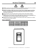
Page 33: ...or property damage CAUTION The Big Ass Fans product warranty will not cover damage or failure caused by improper installation WARNING Exercise caution and common sense when powering the fan Do not connect the fan to a damaged or hazardous power source Do not attempt to resolve electrical malfunctions or failures on your own Contact Big Ass Fans at 1 877 BIG FANS if you have any questions regarding...

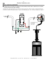
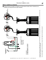
Page 34: ... installing the fan using a typical lighting circuit in which the critical red conductor or traveler is absent an optional Limited Access Controller can be installed allowing the utilization of a typical residential lighting system See Limited Access Application on page 30 BK RD YL RD GND 100 125VAC 1Φ 10A 60Hz FAN SPEED CONTROLLER Acenti ATI06 J BOX mounted locally to fan BLK GRN WHT RED Fan wire...

Page 35: ...ires are paralleled downstream from the fan controller All fans will start or stop simultaneously and operate at the same speed This multi fan application can also be used with a 3 way control configuration as explained on page 32 BK RD YL RD GND 100 125VAC 1Φ 10A 60Hz J BOX mounted locally to fan BLK GRN WHT RED J BOX mounted locally to fan OUT TO REMAINING FANS FAN SPEED CONTROLLER Acenti ATI06 ...

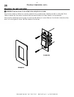
Page 36: ...e from the controller location Install the controller on a flat surface that is readily accessible free from vibration and where there is adequate distance from foreign objects or moving equipment After wiring the controller see previous page mount the controller with two 2 screws Make sure the controller is oriented as shown below Do not overtighten the screws Snap the wallplate to the controller...

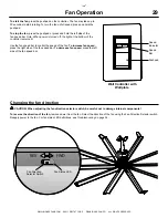
Page 37: ...to control the speed of the fan To increase fan speed press the right side of the fan speed bar To decrease fan speed press the left side of the fan speed bar Fan Operation Wall Controller with Wallplate Pushpad Speed Bar Speed Indicator Changing the fan direction CAUTION When adjusting the fan direction selector switch be careful not to damage internal components To reverse the direction of the f...

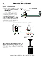
Page 38: ...ing the utilization of the existing 2 wire plus ground circuit black and white shown below Note This scenario is common in residences in which only a light circuit was previously installed Typical Lighting Circuit Note It is essential that the speed controller and remote controller are installed on a common branch circuit The control signal between the devices is modulated on the shared hot conduc...

Page 39: ...e The fan may take up to 30 seconds to start rotating To increase fan speed press and hold the upper portion of the pushpad To decrease fan speed press and hold the lower portion of the pushpad To stop the fan tap the lower portion of the pushpad once To disable the fan pull out the clear tab at the bottom of the controller Note The Limited Access Controller is only necessary if you are utilizing ...

Page 40: ...n utilize the existing 3 way wiring to add the additional control location Note The controller provided with the fan ATI06 does not include a neutral conductor however the optional part required for 3 way operation ATR001 1L does include a neutral conductor This is the only physical difference between the two controllers and can be used for identification if necessary Alternative Wiring Methods co...

Page 41: ...tenance Checklist 1 Ensure all four mounting bolts are present and torqued to 25 ft lb 33 9 N m 2 Ensure airfoils are secured to one another by airfoil retainers 3 Ensure all 20 bolts securing airfoils to fan are present and torqued to 29 ft lb 39 3 N m 4 Ensure all three nuts securing the lower mount to the motor are tight 5 Ensure all winglet hardware is secure 6 Check guy wires if installed for...

Page 42: ...ond Flashes 5 Seconds Off Motor Over current Three 1 Second Flashes 5 Seconds Off Commutation Motor Stall Four 1 Second Flashes 5 Seconds Off Motor Over temperature Five 1 Seconds Flashes 5 Seconds Off Drive Over temperature Status LED Fan Direction Selector Switch General troubleshooting Some issues can be resolved before requesting service Review the below troubleshooting tips before contacting ...

Page 43: ...Fan Model Fan Model Fan Model Serial Serial Serial Location Location Location Date Initials Date Initials Date Initials Annual Maintenance Checklist ...

Page 44: ......

Page 45: ...1L AT106 Guy Wire Kit Company Name Contact Name Shipping Address City State ZIP Phone Number Ext E mail Address I prefer UPS Ground Shipping I prefer UPS Next Day Air Shipping Fully complete this form and then fax to Big Ass Fans at 859 967 1695 A Big Ass Fans representative will phone or e mail you with the total cost of part s and shipping Credit card information will also be obtained at that ti...

Page 46: ......

Page 47: ...ation Fan motor drive and wall controller 10 Years 5 Years All other components Lifetime Lifetime Reasonable labor 1 Year None The 10 Year Warranty Period and 1 Year Labor apply to non residential installations only and requires purchased installation by a factory approved Big Ass Fans certified installer and the submission of installation documentation by such installer A 5 Year Warranty Period w...

Page 48: ...r below 6 If we ask you to ship the fan back to Big Ass Fans for repairs or replacement we will prepay the shipping and insurance for factory installed fans during the first 12 months after the warranty becomes effective however you will have to repackage the fan in such a way that there is no damage to the fan in transit You will be sent any return shipment documentation necessary to help you ret...

Page 49: ...TENTION Under no circumstances will the Big Ass Fan Company be responsible for remedial work necessary to correct installation procedures by others that do not conform to those established by the instructions codes and standards described under items 4 a through 4 d above e Any modification or alteration of or adjustment to the fans fan control and or mounting and installation hardware and or any ...

Page 50: ...been repaired or replaced 2 Operate properly applies to mechanical electrical and structural functions only No guarantee unless and except by separate written agreement is made regarding the dimensions or air movement generated or the appropriateness of the effectiveness of any product for its intended purpose or for the customer s particular application THIS WARRANTY IS EXPRESSLY IN LIEU OF ALL O...

Page 51: ...utside the scope of the warranty or 2 the warranty period has expired If there is no warranty coverage we will send you a detailed letter of explanation We also will charge you for the replacement item plus shipping and handling if you do not return the original item within 10 days of the receipt of the replacement item Instructions for returning the original item 1 Please use the return label tha...

Page 52: ......

Page 53: ...ssigned an RMA by Big Ass Fan Company Customer Service Department The RMA must appear on the outside of the box being returned Items without an RMA will not be accepted Date replacement parts should be shipped if known Please do not request shipment until you are prepared to install you may call us at 1 877 BIG FANS to arrange shipment when you have scheduled installation Acknowledgment of Receipt...

Page 54: ...handling for the original part and all replacements and such invoice will be paid within 15 days of receipt of the same The undersigned agrees to ship to Big Ass Fan Company s location at 2425 Merchant Street Lexington KY 40511 all of the merchandise replaced by Big Ass Fan Company including but not necessarily limited to defective or failed components within 10 working days of the receipt of the ...

Page 55: ...y to be avoided they are also brought to the supervisor s attention and instructed how to bypass the area if required Safety Rules and Regulations listed The facility manager understands all electrical requirements i e breaker size voltage brand main panel space etc and they are in accordance with original Scope of Work and Layout Additional comments Company Job Name Address City State ZIP Contact...

Page 56: ...ues discussed at check in If extension tube is 4 ft 1 2 m or longer guy wires are in place and there is no evidence of a wobble Supervisor has supplied and explained the Installation Guide If not explain The supervisor has explained and I understand how to operate fan including starting stopping speed operation and power disconnect If not explain Time in out and duration are in accordance with Che...

Page 57: ......

Page 58: ......

Page 59: ......

Page 60: ...REV H 2425 Merchant Street Lexington KY 40511 1 877 BIG FANS 1001250101 1001250101 ...

Reviews: