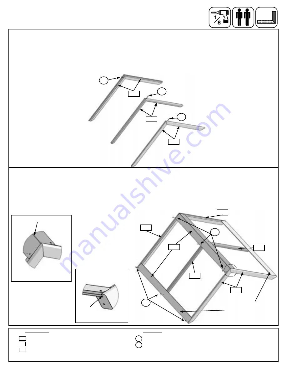
Step 27: Roof Frame Assembly
D:
At the peak attach 1 (C4) Cedar Roofing per side to both Roof Support Assemblies and the Roof Joist Assembly
using 3 (S0) #8 x 7/8” Truss Screws per roofing. (fig. 27.2) One (C4) Cedar Roofing should overlap the other.
(fig. 27.3)
E:
At the bottom of the the Support and Joist Assemblies pre-drill 1” above the existing holes in (C4) Cedar Roofing
and then attach to each side with 3 (S0) #8 x 7/8” Truss Screws per roofing. (fig. 27.2) The bottom of (C4) Cedar
Roofing should be flush to the bottom of each (B25) Roof Support. (fig. 27.4)
A:
Connect 2 (B25) Roof Supports together at the peak using 1 (S4) #8 x 3” Wood Screw. Repeat this to create 2
Roof Support Assemblies. Make sure the supports are tight to each other. (fig. 27.1)
B:
Connect 2 (B26) Roof Joists together at the peak using 1 (S4) #8 x 3” Wood Screw. Make sure the joists are
tight to each other (fig. 27.1)
C:
Place each Roof Support Assembly so the side with the ledge faces in. The Roof Joist Assembly should be in
the middle. (fig. 27.1)
Fig. 27.1
4 x
Roof Support 2 x 3 x 40”
2 x
Roof Joist 2 x 2 x 38-3/4”
4 x
Cedar Roofing 3/8 x 3-1/2 x 47-1/2”
Hardware
Wood Parts
12 x
#8 x 7/8” Truss Screw
3 x
#8 x 3” Wood Screw
B25
S0
B25
S0
B25
B26
S4
Fig. 27.3
S4
S4
Fig. 27.2
Fig. 27.4
B25
B25
B26
S0
B26
C4
Flush
Overlaps
B26
C4
x 3 per side
S4
x 3 per side
B25
Pre-drill pilot hole 1”
above exising holes in
each bottom board
43
Summary of Contents for F23100
Page 2: ......
Page 3: ......
Page 4: ......
Page 5: ......
Page 6: ...Square Assembly...
Page 71: ...NOTES 71...


