5.0
Operation
5.1
1
Re-Picking
a Complete Tower
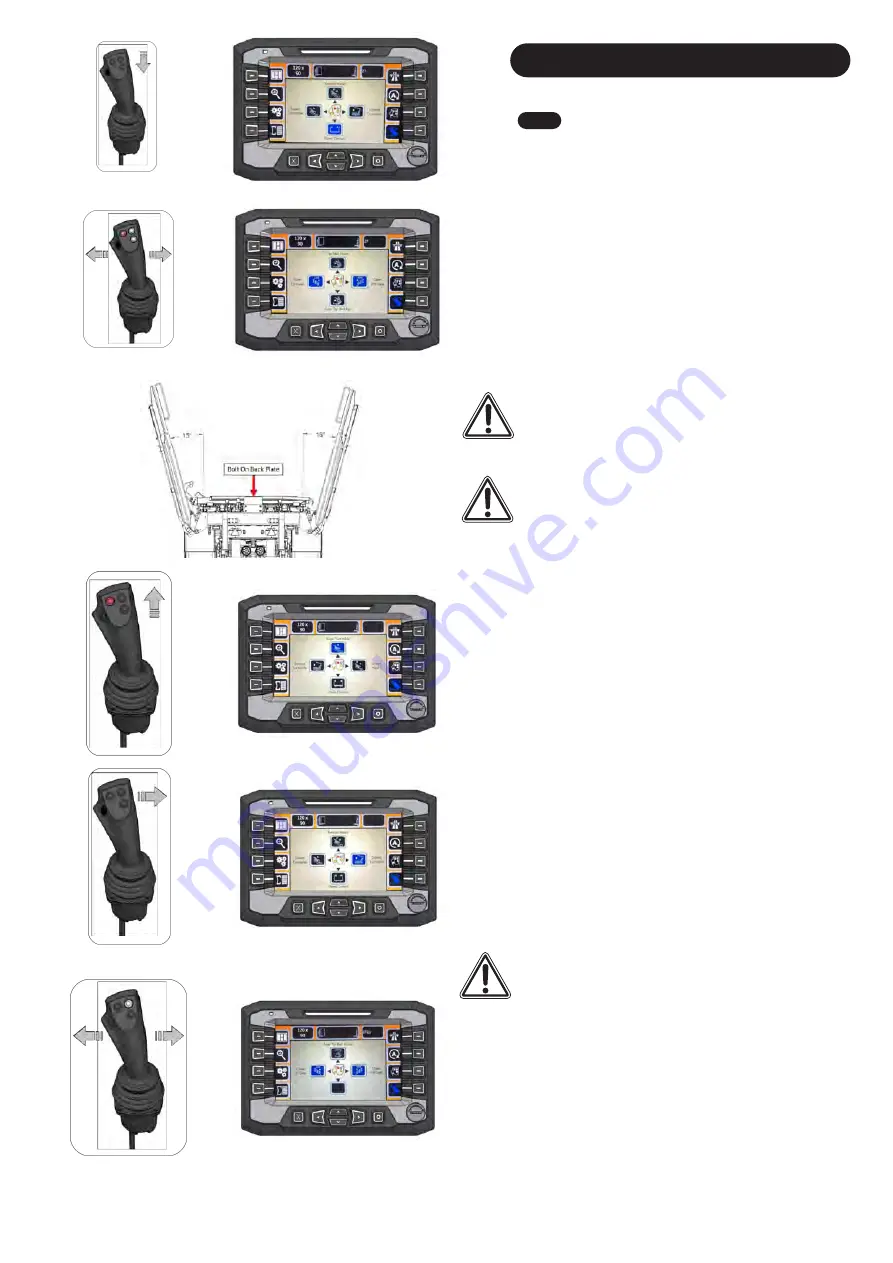
1. Exit ‘Road mode’
and ensure 'Stack Mode' is selected.
2. Hold down the 'BLACK' button and move the joystick
back
(Fig.
43
)
to ‘
Open Clamps
’
.
3.
Move the joystick left and right (
Fig. 44
) to o
pen the
'LH / RH Gates'. Open the 'Side Gates' and 'Rear Clamps'
to a 15 degree angle off vertical.
(
Fig. 45
).
Fig. 43
Fig. 44
Fig. 45
Caution
:
Before proceeding with the re-picking of stacks, it
is recommended to remove the bolt on back plate at the
rear of the Transtacker. This sometimes stop the bales lying
flat on the bed of the 'Platform'.
WARNING
: I
f the bolt on back plate is removed, it MUST be
put back on before you go into 'Auto Mode' or 'Field Manual
Mode'. It may cause damage to the 'Fork System'.
WARNING
: Ensure the Forks are folded down inside the
platform and are to the front of the platform. To perform this,
raise the platform up half way, press and hold the
'RED' button and push forward, this will bring the forks to
the front and release the pressure in the forks raise allowing
the forks to lower. Return platform to home position when
completed.
4.
Hold the 'RED' button down and push the joystick forward
to raise the 'Turntable' to 90 degree (
Fig. 46
).
5.
Hold the 'BLACK' button while moving the joystick to the
right to extend the 'Extension Frame'
(
Fig. 47
).
6. Hold back the joystick to 'Auto Tip Bed Up' till the platform
is half way up
(
Fig. 38
).
C
AUTION
:
Do not reverse with the Transtacker tipped all
the way up. It may damage the 'Lighting Board' at the back if
there is uneven ground.
7. Align the Transtacker evenly in front of the Stacked bales.
when close enough to the stack, raise the platform up to its
maximum and reverse till you have created contact. When
the platform is lying against the stack, hold the
'GREY' button down and move the joystick left and right.
This will 'Close RH / LH Gates'
(
Fig. 48
)
.
Fig. 46
Fig. 47
Fig. 48
15
Summary of Contents for Transtacker 4100
Page 61: ...58...
Page 62: ...59...
Page 63: ...11 0 Hydraulic Systems 11 4 Valve Block Schematic Fig 168 60...
Page 67: ...13 0 Maintenance 13 2 Pickup Grease Points Fig 172 64...
Page 68: ...13 0 Maintenance 13 3 Grab Arm Grease Points Fig 173 65...
Page 69: ...13 0 Maintenance 13 4 Turntable A Frame Grease Points Fig 174 66...
Page 70: ...13 0 Maintenance 13 5 Side Gate Grease Points Fig 175 67...
Page 71: ...13 0 Maintenance 13 6 Rear Clamps Grease Points Fig 176 68...
Page 72: ...13 0 Maintenance 13 7 Chassis Grease Points Fig 177 69...
Page 73: ...13 0 Maintenance 13 8 Platform Grease Points Fig 178 70...
Page 74: ...13 0 Maintenance 13 9 Axle Grease Points Fig 179 71...
Page 84: ...16 0 Operators Notes 81...
Page 85: ...82...
Page 86: ...83...
Page 87: ...84...


