6.8
Proximity Sensors Continued
6.0
Adjustments
Other than adjusting the sensor so it makes a good signal
connection to the trigger target, 4 sensors can be adjusted
to increase speed and efficiency of the Transtacker. Also
these are adjustments are used to help damage happening
to the Transtacker.
6.8.1
Turntable - Middle
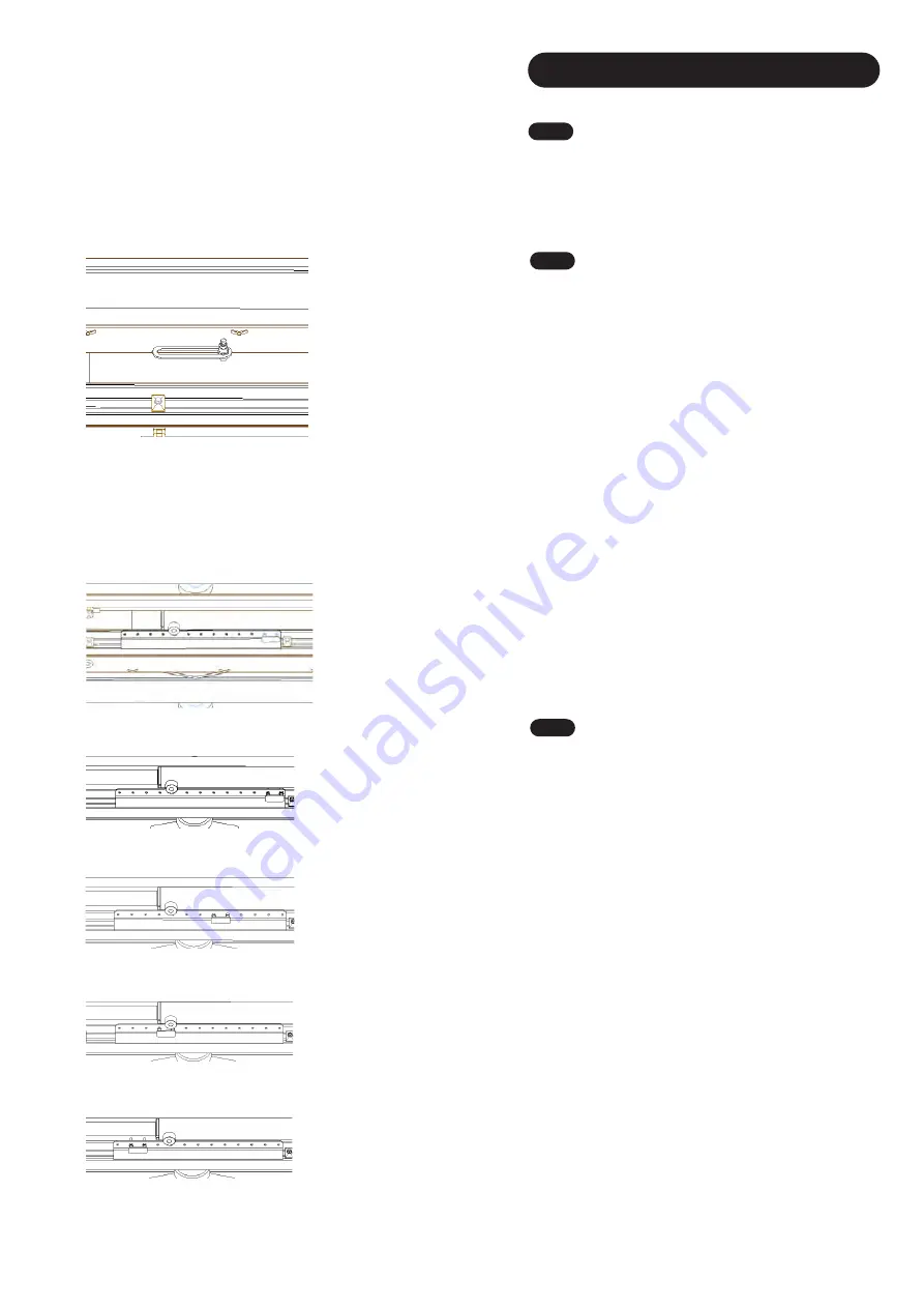
The Turntable - Middle sensor is located within a large
slot
ted
bracket
underneath the platform in the middle
(
Fig.
10
3
).
This is to fine adjust when the turntable comes to
rotate, this is most important on your final layer as the
bales sometimes stick out further to the front.
In this case, if you find the turntable gets stuck in rotation
about half way around, this is because the bales on the
turntable are tight up against the bales on the platform the
this sensor needs adjusting.
To bring the turntable away from the bales on the platform,
slide the sensor towards the front of the Transtacker.
To speed up the turntable rotate cycle you want to have the
turntable traveling the least distance as possible, so slide
the sensor towards the back of the Transtacker. However if
the turntable get stuck as mentioned above, you will need
to slide it forwards again.
Note
: Make sure small adjustments are made at a time to
increase accuracy of adjustments
. Check before adjusting
again.
Note:
This sensor should be factory set. Do not adjust
unless you are a skill
ed
operator and have a great
understanding of the machine.
Fig.
10
3
6.8.2
Turntable - Extend
Th
e Turntable -
Extend
sensor is located with
a large
selection of holds of the inside of the 'Pipe Carrier' in the
middle of the platform.
(
Fig. 10
4
).
This is to fine adjust
how far the turntable extends when its in its full extend
motion. The adjustment of this sensor is important
because it depends on what size bales you are working
with.
When working with 700
mm
high bales, use the closest
holes to the front of the Transtacker, holes 1 & 2 (
Fig.
10
5
).
For 900mm high bales, use holes 5 & 6 from the front of
the Transtacker
(
Fig. 10
6
).
For 1200mm high bales, use holes 9 & 10 from the front
of the Transtacker
(
Fi
g. 10
7
)
.
For 1300mm high bales, use holes 11 & 12 from the front
of the Transtacker
(
Fig.
10
8
).
Note:
This is only a guide. For finer adjustment use other
holes around suggested adjustment.
Note
: Big Bale Co South Ltd does NOT take
responsibility for incorrectly adjusted sensors. Contact
Big Bale Co South Ltd for more in depth detail for
adjustments.
Fig.
10
4
Fig.
10
5
Fig.
10
6
Fig. 10
7
Fig. 10
8
28
Summary of Contents for Transtacker 4100
Page 61: ...58...
Page 62: ...59...
Page 63: ...11 0 Hydraulic Systems 11 4 Valve Block Schematic Fig 168 60...
Page 67: ...13 0 Maintenance 13 2 Pickup Grease Points Fig 172 64...
Page 68: ...13 0 Maintenance 13 3 Grab Arm Grease Points Fig 173 65...
Page 69: ...13 0 Maintenance 13 4 Turntable A Frame Grease Points Fig 174 66...
Page 70: ...13 0 Maintenance 13 5 Side Gate Grease Points Fig 175 67...
Page 71: ...13 0 Maintenance 13 6 Rear Clamps Grease Points Fig 176 68...
Page 72: ...13 0 Maintenance 13 7 Chassis Grease Points Fig 177 69...
Page 73: ...13 0 Maintenance 13 8 Platform Grease Points Fig 178 70...
Page 74: ...13 0 Maintenance 13 9 Axle Grease Points Fig 179 71...
Page 84: ...16 0 Operators Notes 81...
Page 85: ...82...
Page 86: ...83...
Page 87: ...84...


