6.8
Proximity Sensors Continued
6.0
Adjustments
6.8.3
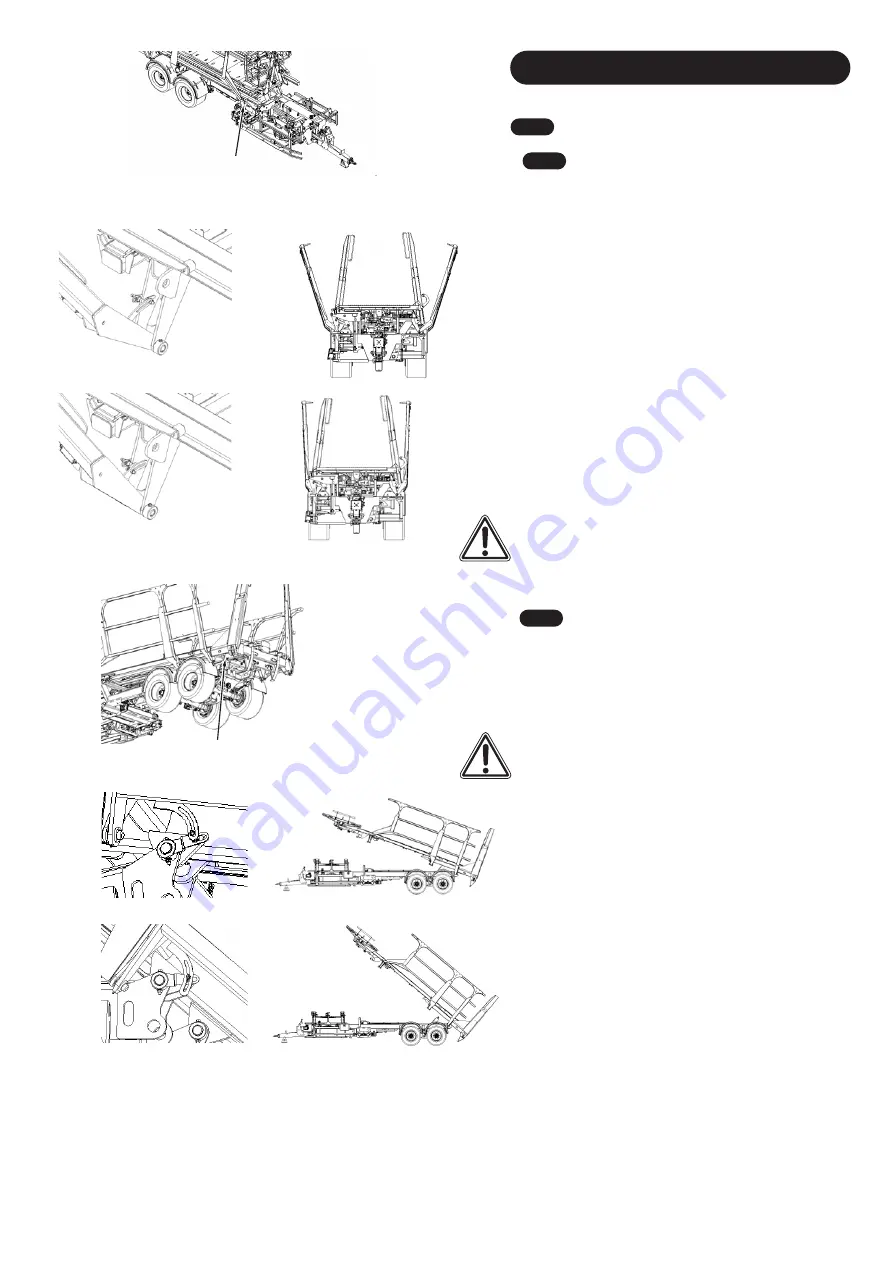
Gates Open LH/RH
The adjustment for the Side Gates are for how much the
Side Gates open. If you find the bales are pushing against
the Side Gates when the turntable is loading them onto the
platform, they will need to be opened more. This will
normally occur when your bales lengths are not consistent
and vary larger then the expected 2500mm. The sensor
adjustment trigger is located on the front leg of each Side
Gate
(
F
ig. 10
9
).
Each Side Gate has its own sensor and
trigger bolt.
To allow the Side Gates to open wider, adjust the trigger
bolt towards the middle of the platform
in its slotted bracket
(
Fi
g. 1
10
). Allowing more movement before it triggers the
sensor.
Refer to
Fig. 11
1
to see the angle of the side gates
relative to the position of the sensor trigger.
If you find the Side Gates are opening too wide and find the
process too slow, the Side Gate trigger bolt need to be
more away from the middle of the platform in its slotted
bracket (
Fig. 1
1
2
).
Refer to
Fig. 11
3
to see the angle of the
side gates relative to the position of the sensor trigger.
CAUTION:
When adjusting these sensors, make sure the
Side Gate open wide enough so the bale doesn't foul
against the Side Gate tines as this could cause damage to
the bale or Transtacker.
Fig. 10
9
Fig. 1
10
Fig.
1
1
2
Trigger Bolt
6.8.4
Tip Bed Up Partial
This sensor is used for the Automatic Part Load system.
This defines the angle the platform will tip to before the
forks will release the layers of bales towards the rear.
This
sensor is located but the back left corner of the chassis
where the platform pivots on the chassis (
Fig. 11
4
).
CAUTION:
When performing a 'Part Load', if the sensor is
not in contactable range, the 'Platform' will lift all the way
up. It is critical that you do NOT lift the Transtacker's
'Platform' over 40 Degrees (
Fig
. 11
8
). This could cause
large damage to the 'Fork System'. Do NOT adjust the
sensor more then where is positioned in
Fig. 11
7
.
Note
: This angle is factory set for the safety of the Fork
system. Only adjust this if you have a full understanding of
the Transtacker or you have been advised by an engineer
at Big Bale Co South Ltd.
If you find the angle of the platform is too high when
performing a Part Load, adjust the sensor bolt so it is
closer to the ground, away from the platform (
Fig. 11
5
).
This will decrease the space between the sensor and the
adjustable bolt. Refer to
Fig. 11
6
to see the angle the
platform will be at the minimum height of the part load.
If you want to increase the angle of the Platform when
performing a Part Load, adjust the sensor trigger bolt away
from the floor, so towards the platform (
F
ig. 11
7
). This will
increase the space between the sensor and the adjustable
bolt. Refer to
Fig. 11
8
to see the angle the platform will be
at when the platform is at its maximum angle of 40 degree.
Note
: Big Bale Co South Ltd does NOT take responsibility
for incorrectly adjusted sensors. Contact Big Bale Co South
Ltd for more in depth detail for adjustments.
Fig.
1
13
Fig. 11
1
Fig.
1
14
Trigger Bolt
Fig.
1
1
5
Fig.
1
1
6
Fig. 11
8
Fig. 11
7
29
Summary of Contents for Transtacker 4100
Page 61: ...58...
Page 62: ...59...
Page 63: ...11 0 Hydraulic Systems 11 4 Valve Block Schematic Fig 168 60...
Page 67: ...13 0 Maintenance 13 2 Pickup Grease Points Fig 172 64...
Page 68: ...13 0 Maintenance 13 3 Grab Arm Grease Points Fig 173 65...
Page 69: ...13 0 Maintenance 13 4 Turntable A Frame Grease Points Fig 174 66...
Page 70: ...13 0 Maintenance 13 5 Side Gate Grease Points Fig 175 67...
Page 71: ...13 0 Maintenance 13 6 Rear Clamps Grease Points Fig 176 68...
Page 72: ...13 0 Maintenance 13 7 Chassis Grease Points Fig 177 69...
Page 73: ...13 0 Maintenance 13 8 Platform Grease Points Fig 178 70...
Page 74: ...13 0 Maintenance 13 9 Axle Grease Points Fig 179 71...
Page 84: ...16 0 Operators Notes 81...
Page 85: ...82...
Page 86: ...83...
Page 87: ...84...


