Fig.
1
20
Fig.
1
2
1
Fig.
12
2
6.0
Adjustments
Fig.
12
3
6.9
Rotary Sensors
For in depth locations of the Rotary sensors,
Refer
to Section 12 Sensor Location.
Before under taking calibration:
•
For the 'Pickup' calibration (0
o
to 180
o
), make sure the
'Guide Bar' and 'Grab Arm' are extended out fully. Also
ensure the 'Turntable' is its home position.
•
For the 'Turntable Lift' calibration (0
o
to 90
o
), make sure
the 'Pickup' is lowered and the 'Tines' are retracted.
•
For the 'Turntable Rotate' calibration (90
o
to 0
o
), make
sure the 'Turntable' is raised to a 25/30 degree angle.
Also ensure the 'Pickup' is lowered and the 'Tines' are
retracted.
All 3 'Rotary Sensors' can be re-calibrated. These sensors will
be calibrated from factory. But due to outside circumstances,
these sensors may need to be re-calibrated.
The positioning of the sensor and magnet are crucial. The
magnet is only rated to 2.5mm off centre to the centre pivot of
the metal work. This is crucial that the sensor is aligned
correctly to the metal work and then the magnet is aligned
correctly to the sensor. To ensure it is correct, line the magnet
up at its home position then operate the function to the
furthest point away from home position, and check the magnet
is still centre. If not, alterations may be needed.
Adjust the sensor to the magnet to maintain a distance of 4 -
10 mm between the target and sensor
(
Fig. 11
9
)
(max range
12mm. If the magnet is too far away from the sensor, it will
give false readings and affect your auto functions. To ensure
this distance is kept constant, the pivot points might need
shimming to stop the gap from increasing or decreasing.
CAUTION:
It is important that the magnet does NOT contact
the sensor or damage and/or malfunction will occur.
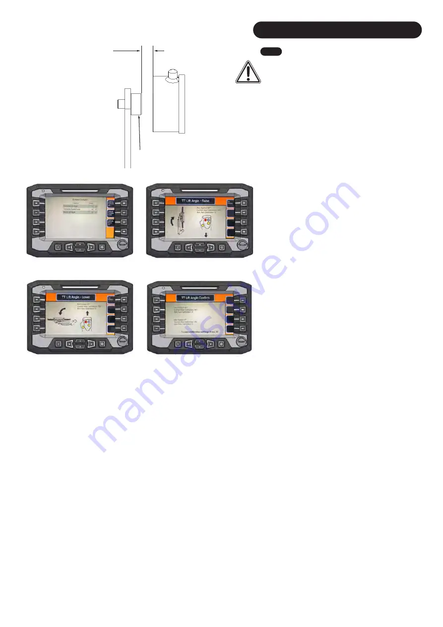
Navigate to 'Diagnostics' and to Page 3 (
Fig. 1
20
). Here you
can navigate to the desired 'Rotary Sensor' calibration. For an
example, the 'Turntable lift' calibration will be used.
1. Once engaging the PTO and the TT Lift Angle Calibration
has been started, pull back on the joystick to raise the
'Turntable' to its most upwards position (
Fig.
1
2
1
). Once the
desired position has been achieved, press ' Set Position'.
Note
: When calibrating a specific rotary sensor, when it is in
motion, on the screen you will notice the 'New Raw
Calibration' value will increase or decrease depending on the
direction of the motion. If this value is 0 or not moving, there
may be an issue with the sensor.
2.
This will bring you to the next stage. Push forward on the
joystick to lower the 'Turntable' to its lowest position (
Fig.
12
2
). Again press the 'Set Position' button.
3.
To save these final calibration settings, press the 'O'
button
as instructed on the screen (
Fig. 123
). If these changes have
no
t
worked
, c
ontact Big Bale Co South Ltd for further advice.
Min
:
4
mm
Max: 12mm
Fig.
11
9
Sensor
Magnet
Note:
On the 'Angle Confirm' page (
Fig. 123
), it will show you two sets of 'Raw Valves'.
This is always between 0 and 512. This represents the 512 positions in the 360 degree
motion the sensor can work in. The 'Current Raw Calibration' is the value before it was
calibrated. The 'New Raw Calibration' value is the new calibration movement you have
just saved. If the sensor or magnet has been replaced or taken off, it may be out of line
then previously. You will notice the difference between the set of old and new raw
values. If the sensor is in line and didn't need calibrated then these valves may not
change.
Note
:
As the sensor can only read from 0 - 512 in a circle (360 degrees), it has the
potential to jump from 512 to 0 when in calibration. This will not allow the sensor to work
correctly. For an example: If the sensor moves 90 degrees (130 positions) it will have to
start on a raw value of 382 or lower if its raw value will increase when finishing the
calibration. The end raw value of this will be 512 and should not pass 512. If this
scenario is happening, with a pair of pliers, twist the magnet in small increments until
the calibration does not cross the 0 to 512 mark.
30
Summary of Contents for Transtacker 4100
Page 61: ...58...
Page 62: ...59...
Page 63: ...11 0 Hydraulic Systems 11 4 Valve Block Schematic Fig 168 60...
Page 67: ...13 0 Maintenance 13 2 Pickup Grease Points Fig 172 64...
Page 68: ...13 0 Maintenance 13 3 Grab Arm Grease Points Fig 173 65...
Page 69: ...13 0 Maintenance 13 4 Turntable A Frame Grease Points Fig 174 66...
Page 70: ...13 0 Maintenance 13 5 Side Gate Grease Points Fig 175 67...
Page 71: ...13 0 Maintenance 13 6 Rear Clamps Grease Points Fig 176 68...
Page 72: ...13 0 Maintenance 13 7 Chassis Grease Points Fig 177 69...
Page 73: ...13 0 Maintenance 13 8 Platform Grease Points Fig 178 70...
Page 74: ...13 0 Maintenance 13 9 Axle Grease Points Fig 179 71...
Page 84: ...16 0 Operators Notes 81...
Page 85: ...82...
Page 86: ...83...
Page 87: ...84...


