9
.0
Tips and Information
9
.
1
Side by Side Stacking
To stack side by side, either side gate can be lowered to
enable closer placing of stacks. Removal of either side gate
pin is required (
see
S
ection
6.15
), however do not lower the
side gate until the trailer is tipped to approximately 45
degrees. This will ensure all the bales are secure by inter
layer friction.
Once the trailer is tipped halfway and the side gate has been
opened, manoeuvre the stack into position before raising the
platform fully. Remember the machine will roll back a
fraction when the machine fully tips.
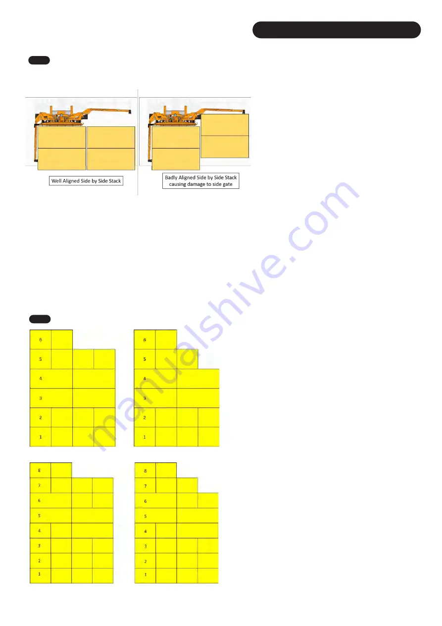
The alignment of the adjacent stacks is important as to not
over stress the side gates on existing stacks (
Fig.
1
5
2
). Very
poorly aligned stacks will cause damage to the side gate, as
seen on the right side of
Fig. 1
5
2
.
NOTE
: Any damage caused to side gate by badly aligned stacks is the operator’s responsibility. The operator should always aim to align the new
stack with the existing stack/s and not stack further behind. The operator will also need to be aware of the side gate whilst manoeuvring the machine
into place as to no stress the side gate on existing stacks.
NOTE
: Be careful to not overpower the rear clamps when releasing a stack. Overpowering and opening the rear clamps excessively will cause the
whole trailer to be pushed sideways and will cause excessive stress on the machine. Once the clamping force is released, the clamps should slide
out from underneath the stack as you slowly pull forward away from the stack.
NOTE
: Should there be road travel between the stack site and the collection site, it is the operator’s responsibility to ensure both side gate road pins
are fitted.
9
.
2
Starting
O
ff
S
tack
This section gives operators who are new to stacking some basic ideas
as how to ‘build’ a stack. This is only a guide and the main person to
discuss the stack configuration with the is the person who is taking the
stacks down and loading.
Layer 1 (
Fig.
15
3
) should always be an ‘Auto-stack With Tie’
regardless of the bale size. This ensures the bales sits across the forks
if they are being used.
Fig. 15
3
& 15
4
shows two examples of how to
start a stack using two separate bale sizes. This stack configuration
will give you a stable stack to tip other loads against. When counting
layers, the layers are referenced by starting at the layer in the rear
clamps. As shown in
Fig. 15
3
& 15
4
, once the stack is erected, Layer
1 is the layer that is in contact with the ground. In the examples, the
stack is being added to from right to left.
NOTE
: If there is only one tied/not tied layer on the top, depending on
the grab style it can be very difficult to dissemble the stack.
Alternatively, you can have just a single bale as the final layer which
reduces the risk of a bale falling of the back of the stack.
If you are building a large stack, it is recommended to tie the first two
stacks and to stack them all the same way. If the stack is going to
stand for a significant period of time, the final stack can also be tied to
secure the entire stack.
If you’re stacking on sloping ground, it’s much easier to build the stack
working up the hill where possible. This way the bales will naturally
want to lean backwards and keep the stack standing.
With 1.2x1.3m bales, you will only get 5 layers on the trailer unless the
bales are rolled through 90 degrees so the strings are around the sides
of the bales instead of being around the top and bottom of the bales.
You may find stacking the bales with the strings on the side much
easier as the bales tend to be much more level and even over the
length of the bale.
Fig. 1
5
2
Fig. 1
5
3
Fig. 1
5
4
48
Summary of Contents for Transtacker 4100
Page 61: ...58...
Page 62: ...59...
Page 63: ...11 0 Hydraulic Systems 11 4 Valve Block Schematic Fig 168 60...
Page 67: ...13 0 Maintenance 13 2 Pickup Grease Points Fig 172 64...
Page 68: ...13 0 Maintenance 13 3 Grab Arm Grease Points Fig 173 65...
Page 69: ...13 0 Maintenance 13 4 Turntable A Frame Grease Points Fig 174 66...
Page 70: ...13 0 Maintenance 13 5 Side Gate Grease Points Fig 175 67...
Page 71: ...13 0 Maintenance 13 6 Rear Clamps Grease Points Fig 176 68...
Page 72: ...13 0 Maintenance 13 7 Chassis Grease Points Fig 177 69...
Page 73: ...13 0 Maintenance 13 8 Platform Grease Points Fig 178 70...
Page 74: ...13 0 Maintenance 13 9 Axle Grease Points Fig 179 71...
Page 84: ...16 0 Operators Notes 81...
Page 85: ...82...
Page 86: ...83...
Page 87: ...84...


