1
1
.0
Hydraulic
System
1
1
.
1
Hydraulic Standby Pressure
(Load Sensing)
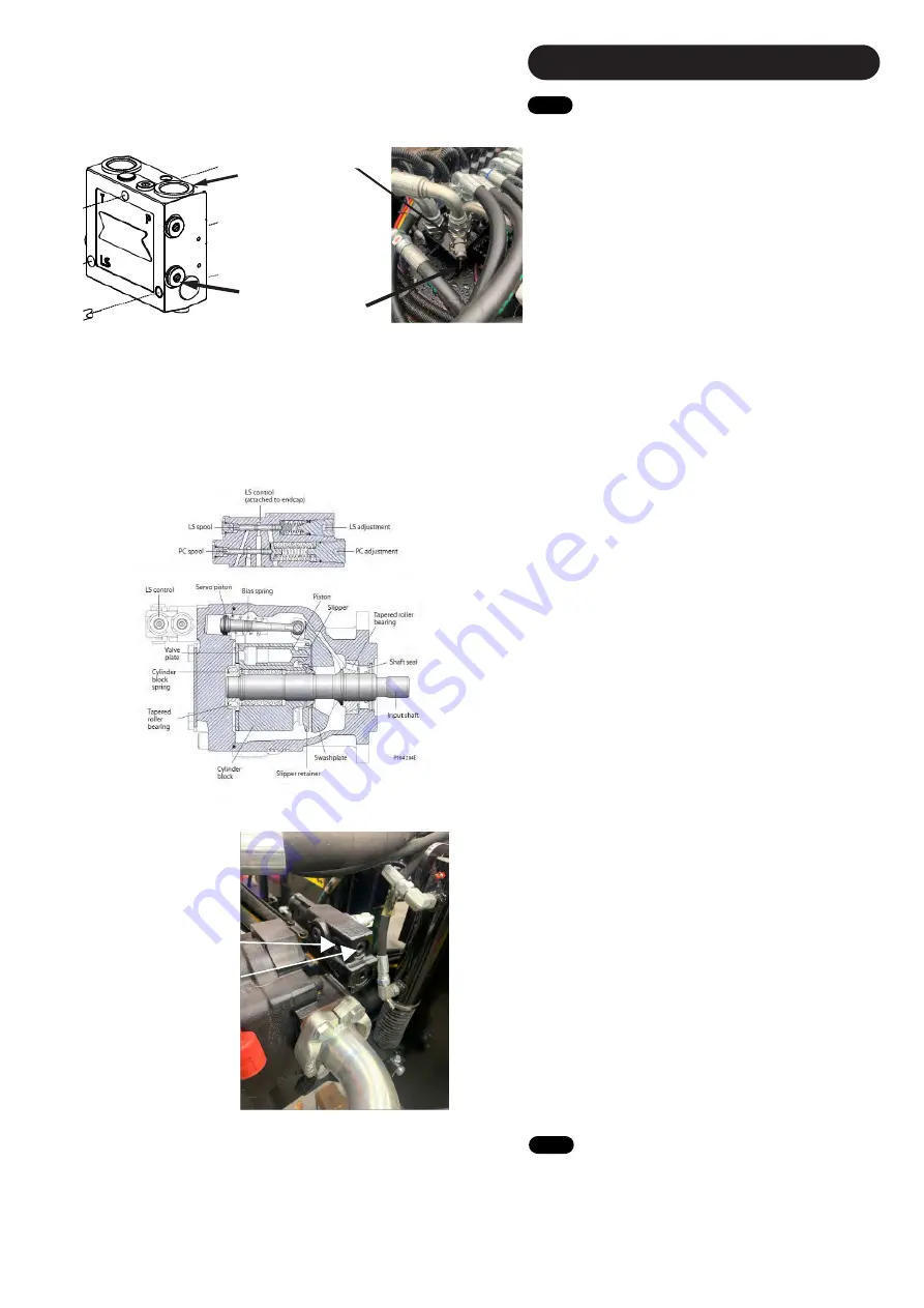
3/4” Test T-Piece
can be attached to
this port.
Do NOT attempt to change the Standby Pressure of the
Hydraulic Pump without Authorization. Big Bale Co South
Ltd will not take responsibility of incorrectly adjusted
Standby Pressure. You must have a full understanding of
the machines hydraulic system to attempt further into this
stage.
How to adjust standby pressure on hydraulic pump. Where
to fit hydraulic fitting to measure standby pressure.
Use a 40BAR pressure gauge to read pressure but DON’T
operate any functions on the Transtacker Hydraulic system
otherwise it will blow pressure gauge.
Checking Standby Pressure
Ensure the PTO is turned off at this point.
To check the standby pressure you will require a test point
to either screw into the valve block. The fitting must be ¼”
BSP
,
Fig.
1
6
1
shows the 2 different locations you can use.
You will need to remove the current plug in the system.
Alternatively depending on the hydraulic fittings you have
available you could put a ¾ Male-Female adaptor with a
test point and connect that into between the hose and the
adaptor fitted to the valve block inlet
(
Fig.
1
6
1
).
Once connected the 0-40bar range gauge. You can now
engage the PTO and read the pressure accordingly.
WARNING: DO NOT OPERATE ANY FUNCTION WHILST
0-40 BAR GAUGE IS CONNECTED TO THE SYSTEM AS
THAT WILL OVER PRESSURE THE GAUGE.
The standby pressure should be 20 ± 2 bar. If the standby
pressure is outside that range then you will need to adjust
the standby pressure relief valve on the pump accordingly.
Adjusting Standby Pressure
To adjust the standby pressure you will need to alter the
relief valve on the pump. On the pump there are two relief
valves, one for the standby pressure and the other for the
pump pressure relief valve.
Fig.
1
6
2
shows the location of
the Load Sensing Spool (LS) and Pressure Compensating
(PC) Spool.
To adjust the Load Sensing Control (LS adjustment) there
is a grub screw which first needs to be loose to allow the
adjustment to be made
(
Fig.
1
6
3
)
.
Then you simply turn
clockwise to increase the pressure or anticlockwise to
decrease the pressure.
1/4” Test point can
replace this plug.
Fig.
1
6
1
Fig.
1
6
2
Fig.
1
6
3
Grub Screw
Standby Adjustment
(LS Control)
1
1
.
2
General Hydraulic Information
There are two hydraulic filters on the machine. A return filter located in the top of the hydraulic tank and an inline pressure filter mounted to the drawbar
in front of the valve block. The return filter should be changed every year and the pressure filter every other year.
The maximum hydraulic pressure of a Transtacker is 210BAR. Also all hydraulic hoses are 2 wire other than the fork hoses which is a single wire. This
information is relevant should you need to replace any hydraulic hoses.
The grade of oil required is Hydraulic HV46.
56
Summary of Contents for Transtacker 4100
Page 61: ...58...
Page 62: ...59...
Page 63: ...11 0 Hydraulic Systems 11 4 Valve Block Schematic Fig 168 60...
Page 67: ...13 0 Maintenance 13 2 Pickup Grease Points Fig 172 64...
Page 68: ...13 0 Maintenance 13 3 Grab Arm Grease Points Fig 173 65...
Page 69: ...13 0 Maintenance 13 4 Turntable A Frame Grease Points Fig 174 66...
Page 70: ...13 0 Maintenance 13 5 Side Gate Grease Points Fig 175 67...
Page 71: ...13 0 Maintenance 13 6 Rear Clamps Grease Points Fig 176 68...
Page 72: ...13 0 Maintenance 13 7 Chassis Grease Points Fig 177 69...
Page 73: ...13 0 Maintenance 13 8 Platform Grease Points Fig 178 70...
Page 74: ...13 0 Maintenance 13 9 Axle Grease Points Fig 179 71...
Page 84: ...16 0 Operators Notes 81...
Page 85: ...82...
Page 86: ...83...
Page 87: ...84...


