39
6.1.5 Pickup Shoe adjustment
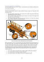
The Pickup Shoe is the black bar on the bottom of the pickup. It is generally only needed when picking
up 1.2x1.3m bales as the tines will be higher in the bale in order for the pickup height to be correct
for the Turntable.
You may fin
d during the ‘Auto
-
Pickup’ sequence, the bale may try and roll away from the pickup rather
than lift with the pickup. To prevent this, take two 13mm spanners and remove the M8 bolts and slide
the shoe down. If you’re doing this on your own
, a jack may be handy to support the weight of the
pickup shoe and stop it falling totally out.
There are two possible holes in the pickup shoe. Depending on the ground clearance required, choose
the appropriate holes to meet the amount of support required.
6.1.6 Turntable Stop Adjustment
The black Stop on the left hand side of the Turntable slides in and out of the Turntable. This Stop can
be used to ‘tighten’ the stack if you feel there are gaps between the two bales during the ‘Auto
-
Stack’
sequence. Be aware of making the bales too tight, otherwise you will find that
during the ‘Auto
-
Pickup’
sequence, the machine will not be able to complete the sequence when placing the final bale on the
turntable.
The pickup won’t retract the
tines because the pickup would not have pushed the bale far
enough onto the turntable. In this case, you will need to slide the bar out of one hole. The Turntable
Stop should only need adjusting in the initial setup or during the scenario described below.
When picking up 1.2x1.3m bales, if the bales are rolled through 90 degrees so when you pick them up,
the strings are around the sides of the bales rather than top to bottom, the Stop will need to be slid
out approximately 0.2m to compensate in the difference for the bale width.
6.2 Stack Configurations
This section gives operators who are new to stacking some basic ideas as how to
‘
build
’
a stack. This
is only a guide and the main person to discuss the stack configuration with the is the person who is
taking the stacks down and loading.
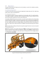
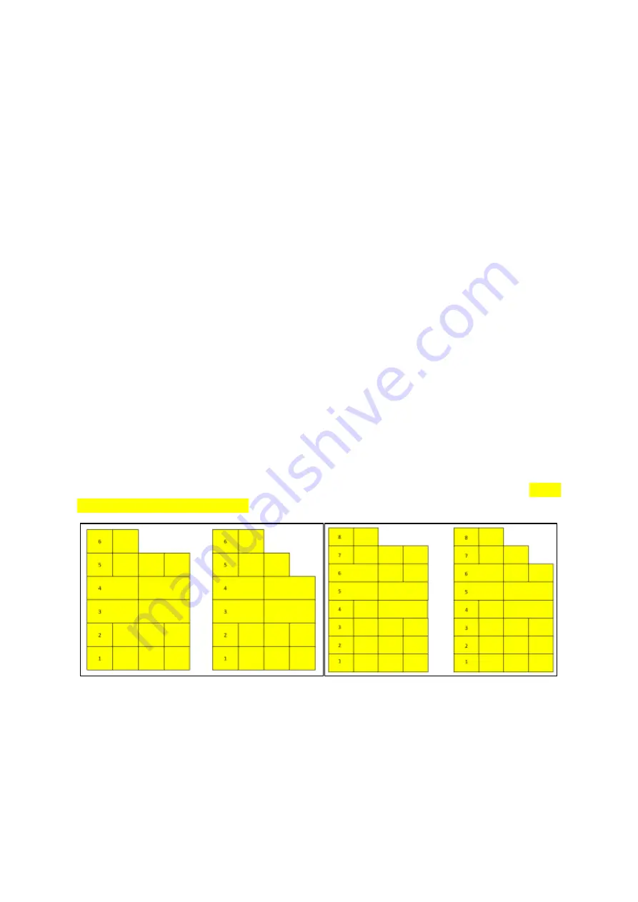
Figure 55: Stack Configurations examples for 1.2x1.3m bales (left) and 1.2x0.9m bales (right)
Layer 1 (Figure 55) should always be an
‘Auto
-stack With T
ie’
regardless of the bale size. This ensures
the bales sits across the forks if they are being used. Figure 55 shows two examples of how to start a
stack using two separate bale sizes. This stack configuration will give you a stable stack to tip other
loads against. When counting layers, the layers are referenced by starting at the layer in the rear
clamps. As shown in Figure 55, once the stack is erected, Layer 1 is the layer that is in contact with
the ground. In the examples, the stack is being added to from right to left.
Summary of Contents for Transtacker
Page 7: ...7 3 0 Machine Overview Figure 1 Transtacker Overview...
Page 43: ...43 Figure 59 Auto Settings Screen...
Page 57: ...57 8 1 Auto Pickup Sequence Figure 69 Auto Pickup Diagram...
Page 58: ...58 8 2 Auto Stack Sequence both with and without tie Figure 70 Auto Stack Diagram...
Page 59: ...59 8 3 Auto Lower Turntable Figure 71 Auto Lower Turntable Diagram...
Page 60: ...60 8 4 Auto Open Sequence Figure 72 Auto Open Diagram...
Page 61: ...61 8 5 Auto Tip Bed Down Sequence Figure 73 Auto Tip Bed Down Diagram...
Page 62: ...62 8 6 Road Mode Sequence Figure 74 Road Mode Diagram...

