56
8.0
Software Diagrams.
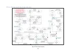
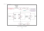
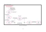
To aid with diagnostics, the software diagrams should help the operator locate where the issue
within the auto sequence and combined with section 9.0 Troubleshooting may help resolve the
issue. The software diagrams in this section only apply to the auto functions.
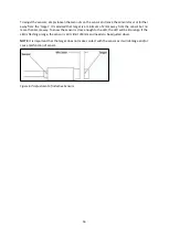
By using diagrams and the top right corner of the screen (Figure 8), along with the key below (Table
10), you should be able to fault find or fine tune the machine. You should be able to locate which
setting/sensor is causing the fault and should your
machine ‘pause’ during an
auto sequence, then
you should be able to locate where within the diagram it is.
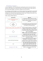
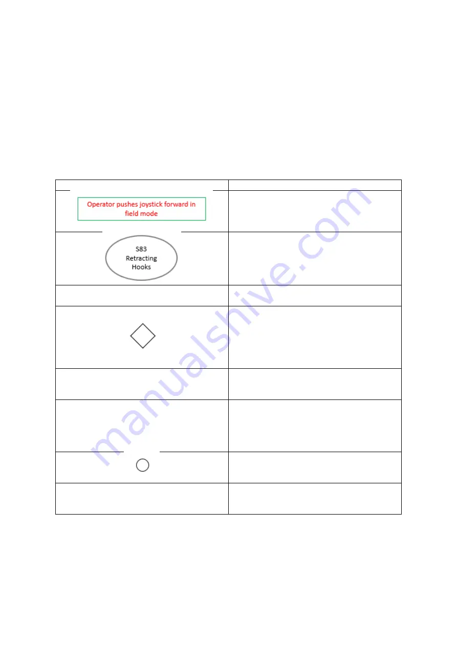
Table 10: Key to Software Diagrams
Symbol/Text
Meaning
The rectangular shape is used to show what
input starts the auto sequence. The text inside
signifies what the input must be to start the
sequence.
This oval symbol is the function the machine is
performing depending upon the text inside.
This example is ‘
Retracting H
ooks’
.
Operator pushes joystick forward in field mode
Red coloured text anywhere on the software
diagrams requires input from the operator.
The diamond shape means a decision is being
made by the software depending upon sensor
and/or timer feedback.
NOTE
: To help you with making the decision,
you may need to refer to the
‘
Sensor Status
’
page to know the status of the sensor.
Pickup Hold Angle (90
o
)
Blue text displayed anywhere on the software
diagrams
are the ‘Extra Settings’
which make
them easier to locate.
Auto Insert Tines Timer (3 secs)
The text displayed around the oval shapes in
the diagrams is the feedback that the ECU
needs to know to confirm that the function is
completed. Terminology matches the screen to
assist with finding the necessary setting.
The circle is wher
e ‘parallel’ functions will
happen. Parallel means the machine will
perform multiple functions at the same time.
Only used on 2
nd
/3
rd
bale
Purple text are comments to help explain the
function and when certain functions will
happen.
Summary of Contents for Transtacker
Page 7: ...7 3 0 Machine Overview Figure 1 Transtacker Overview...
Page 43: ...43 Figure 59 Auto Settings Screen...
Page 57: ...57 8 1 Auto Pickup Sequence Figure 69 Auto Pickup Diagram...
Page 58: ...58 8 2 Auto Stack Sequence both with and without tie Figure 70 Auto Stack Diagram...
Page 59: ...59 8 3 Auto Lower Turntable Figure 71 Auto Lower Turntable Diagram...
Page 60: ...60 8 4 Auto Open Sequence Figure 72 Auto Open Diagram...
Page 61: ...61 8 5 Auto Tip Bed Down Sequence Figure 73 Auto Tip Bed Down Diagram...
Page 62: ...62 8 6 Road Mode Sequence Figure 74 Road Mode Diagram...

