46
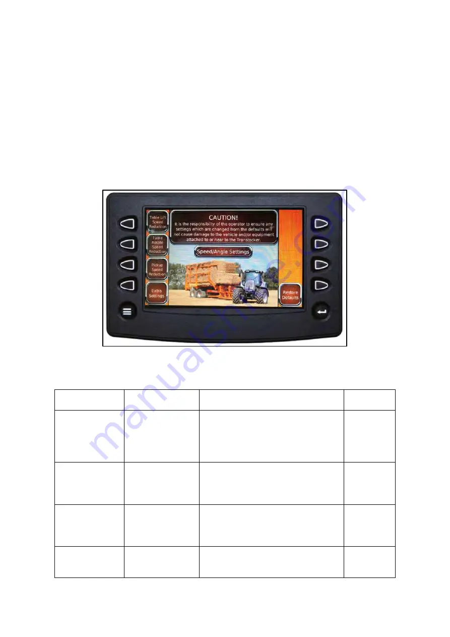
6.3.3 Speed/Angle Settings
This page gives you adjustments
to the ‘speed reductions’ or proportional speed control
of pickup
lift/lower, turntable lift/lower and turntable rotate clockwise/anticlockwise. It is advised that without
a competent operator, none of these settings should be changed.
These proportional speed reduction settings slow down the beginning and end of the cylinder strokes
to make the machine smoother in operation and exerts less stress on the machine.
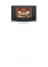
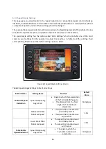
The speed/angle setting has the option called
‘Extra Settings’ which is prob
ably one of the most
common used settings for the operator to adjust the machine. In Table 8, all the settings, their
corresponding functions and the default setting value are listed.
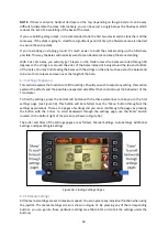
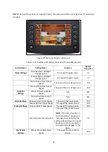
Figure 60: Speed/Angle Settings Screen
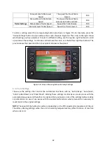
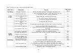
Table 8: Speed/Angle Settings Table of all settings
Button Name
Setting Name
Function
Default
Value
Table Lift Speed
Reduction
Speed Dampening
Angle Start
•
Angle to which the acceleration
of the Turntable lift happens
•
The distance from the final
angle, the Turntable will
decelerate
16 degrees
Raise Stack Table
Minimum Speed
•
The speed the Turntable raise
will initially start at
•
The speed the Turntable raise
will finish at
42%
Lower Stack Table
Minimum Speed
•
The speed the Turntable lower
will initially start at
•
The speed the Turntable lower
will finish at
30%
Table Rotate
Speed Reduction
Speed Dampening
Angle Start
•
The angle to which the
Turntable rotation will
accelerate
16 Degrees
Summary of Contents for Transtacker
Page 7: ...7 3 0 Machine Overview Figure 1 Transtacker Overview...
Page 43: ...43 Figure 59 Auto Settings Screen...
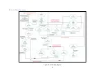
Page 57: ...57 8 1 Auto Pickup Sequence Figure 69 Auto Pickup Diagram...
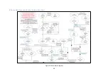
Page 58: ...58 8 2 Auto Stack Sequence both with and without tie Figure 70 Auto Stack Diagram...
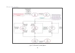
Page 59: ...59 8 3 Auto Lower Turntable Figure 71 Auto Lower Turntable Diagram...
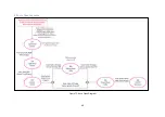
Page 60: ...60 8 4 Auto Open Sequence Figure 72 Auto Open Diagram...
Page 61: ...61 8 5 Auto Tip Bed Down Sequence Figure 73 Auto Tip Bed Down Diagram...
Page 62: ...62 8 6 Road Mode Sequence Figure 74 Road Mode Diagram...


