background image

HOW TO USE THIS GUIDE 


This guide is presented in a format intended to be easy to decipher for the 

intermediate to advanced model builder who is passably familiar, at least, with lighting 
diagrams and electrical current flow. For the beginner, this kit is certainly usable! But 
you might want to take some time to gather some information and familiarize yourself 
with basic terminology and knowledge on electrical diagrams and current. This is 
especially true if you intend to deviate at all from the instructions for this kit. 

The guide is presented in an “easy-to-read” format where the builder can simply 

solder the string of lights, as marked, and connect them to the color-coded terminal 
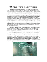
points, as marked. However, to ensure better connections, it is HIGHLY RECOMMENDED 
that the model builder solder the connecting wires together whenever possible! 
Terminal connections may not always be absolutely secure. Twisting the ends of wires 
together may also create some issues getting good connections. It is much more 
preferable to solder the end connections together whenever possible before inserting 
the wires into the corresponding terminal points. If connecting only a single wire, 
particularly wire wrapping wire (thin shielded wire) or magnet wire (thin coated wire), 
we recommend making a tiny “hook” by carefully curving the end of the wire back on 
itself to fit into the terminal. This helps to hold the wire in place so it doesn’t slip out of 
the screw lock. 

Ultimately, it’s up to you, the builder, to choose how best to secure your wiring. 

We’ve made every possible attempt to make this process as simple as possible for 
builders of all levels. But you must choose the most secure method you prefer for your 
building style to ensure the best, lasting connection. We will make suggestions in the 
guide to help whenever possible/necessary. 

There may be some times when a group of wires do not easily fit into a terminal, 

particularly on the main board. You may choose to make a “ponytail” by bringing 
together all the wires for that terminal and soldering them together or using a wire nut 
with a single short additional wire leading out which will connect to the terminal and 
supply current to all the connected wires. Instead of, say, 4 wires going into one 
terminal, you now have only the one.  
 

A note on magnet wire and/or wire wrapping wire: Many of the solutions used for wiring LED’s in this kit 
involve the use of magnet wire or wire wrapping wire, both a form a thin, highly conductive wire used to 
reduce the visible profile of standard 24-28 gauge wire inside the model. Magnet wire is wonderful stuff! 
But, it’s also thin and potentially fragile. Pieces prewired with magnet wire (red and green in this kit) 
should be handled delicately so as not to damage the connections. Also note that, while all magnet wire 
pieces included have been prepared for connection, magnet wire can be a bit challenging to “strip” to 
prepare for proper connection. If your prewired LED’s with magnet wire don’t seem to be functioning, 
please double check to make sure the colored wire shielding has been stripped away at its connecting 
point and, if not, carefully use a #11 hobby blade to scrape away any shielding to expose wires as 
necessary.   

Summary of Contents for 1701-E SOVERIGN COMMANDER Series

Page 1: ...Big Easy Modeling Solutions Presents THE 1701 E SOVERIGN COMMANDER SERIES BOARD ...

Page 2: ... possible though some soldering will be necessary to get the results you want Basic soldering skills are assumed with this kit but if you need help or are not as experienced feel free to contact us at Big Easy and we ll do our best to assist you We are confident that anyone can learn the skills necessary to make this lighting kit work for your build and we ll help you in any way we can This manual...

Page 3: ...ow best to secure your wiring We ve made every possible attempt to make this process as simple as possible for builders of all levels But you must choose the most secure method you prefer for your building style to ensure the best lasting connection We will make suggestions in the guide to help whenever possible necessary There may be some times when a group of wires do not easily fit into a termi...

Page 4: ...tary tool such as a Dremel for the majority of them but you should also need a drill or pin vise and a jeweler s file Here is a useful chart for non metric drill bit sizes to accommodate standard size LED s if you need to change any mounting hole sizes 1 8mm 2mm LED 3 32 Drill bit 3mm LED 1 8 Drill bit 5mm LED 13 64 Drill bit WE ALSO RECOMMEND MARKING THE INSIDE OF THE MODEL DESIGNATING WHERE YOU ...

Page 5: ...sistors for the included power source Deflector Impulse resistors may be different as those effects connect to a 5V terminal instead of the higher 9V or 12V Notice on your LED that each has a long metal lead and a shorter one In almost all cases the longer leg is positive and the shorter leg is negative Also on 3mm and 5mm LED s there is a noticeable indentation on the very low ring around the bas...

Page 6: ...eparate the two again Next repeat the same process with the wire by coiling about a cm of exposed stripped wire around the other end of the resistor and adding solder the same way Then repeat this step for the negative wire and LED leg NOTE you only need a resistor on one LED leg Again trim off any excess LED leg metal Finally twist your attached wires tightly for a tidy finish strip off a little ...

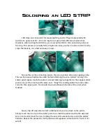
Page 7: ...s where we will add some solder before attaching the wire called tinning the solder point Again touch the solder coil and soldering tip together to the copper solder points not just the iron tip with solder on it Drag the melting solder from the solder coil onto the copper pads You should have a small bead of solder at the point when finished Next strip off only about a half a millimeter of wire t...

Page 8: ...he LED s in say your saucer section can have one positive wire spliced from each LED and strip to the next with only a single positive wire having to go back into the 12V terminal instead of all of the positive wires from each LED Talk about a space saver The negative wires will each go to their respective effects terminal But you can share the wires from each effect as well if multiple LED s have...

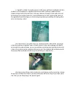
Page 9: ... causing a short One more trick is using LED strips as a contact point for other LED s as long as either the positive or negative wires or both connect to the same voltage and effects terminal In the picture below you can see where an LED has been attached to the LED strip on the contact points opposite of the wire end The attached LED will behave with the same effect and button functions as the L...

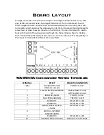
Page 10: ...hen inserting it into the terminal so that it s double thick That will help the terminal have more to secure to Also note that the polarity of the output terminal will be different for some effects SOVEREIGN Commander Series Terminals TERMINAL EFFECT POLARITY CONNECTION 1 RX NAVIGATION LIGHT Alternate version POSITVE to LED 2 SWITCH INTERIOR DIMMER UP SWITCH WIRE 1 HERE SWITCH WIRE 2 to GR 3 IMPUL...

Page 11: ...fect All three LED s work in conjunction to make the effect work Just arrange them in a triangle inside the front of the nacelle adjusting them until you are satisfied with the look The NEGATIVE leg of your bussard LED 1 will connect here The POSITIVE leg with proper resistor will connect to 9V 6 BUSSARD 2 This terminal along with terminals 5 and 9 controls one of the three LED s used in the bussa...

Page 12: ...INTERIOR STRIPS This terminal controls the interior LED lighting most commonly done with LED strip lighting Connect the NEGATIVE wire from your LED strips or LED s to this terminal The POSITIVE wire will connect to the 9V terminal If you are using standard LED s instead of strips you will need to use proper resistors LED strips don t require any more resistance The brightness is controlled with th...

Page 13: ...For any questions contact us anytime through our Facebook page or at www bigeasymodelingsolutions com Thank you and happy modeling ...

Reviews: