


12’–24’ BASIC 6
®
WWW.BIGASSFANS.COM ©2012 DELTA T CORP. ALL RIGHTS RESERVED
26
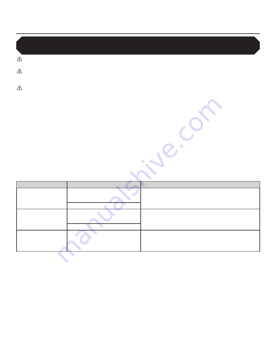
Power wiring guidelines
WARNING: Installation must comply with specifications from National Electrical Codes and standards (NEC, VDE, BSI,
etc.) regarding wire types, conductor sizes, branch circuit protection, and disconnecting devices.
WARNING: To avoid a possible shock hazard and/or nuisance tripping caused by induced voltages, unused wires in the
conduit must be grounded at both ends. For the same reason, fan controller output wires should not share a conduit with
another fan controllers output leads, or other power circuits (lighting, motors, etc.).
CAUTION: MC or “Metal clad” cable cannot be used for controller output/motor leads. Both stranded and solid core
varieties must be avoided. Do not use solid core cable of any size or insulation class for motor wiring. Use of such types
of cabling may result in nuisance tripping or premature equipment failure.
A variety of cable types are acceptable for variable frequency drive installations.
For many installations, unshielded cable is adequate
if it can be separated from sensitive circuits.
In all cases, parallel runs of control and motor cabling should be avoided when unshielded
cable is used. Do not use cable with an insulation thickness of less than 15 mils.
•
UL installations in 50ºC ambient must use 600V, 75ºC or 90ºC wire.
•
UL installations in 40ºC ambient should use 600V, 75ºC or 90ºC wire.
Acceptable unshielded types
THHN, THNW, or similar wire is acceptable for drive installations in dry environments if adequate free air space and/or conduit fill rate
limits are provided.
Do not use THHN or similarly coated wire in wet areas.
Any wire chosen must have a minimum insulation thickness
of 15 mils and should not have large variations in insulation concentricity.
Acceptable shielded types
The drain conductor included with shielded cables must be connected to both the motor frame and the PE/Ground terminal of the
Variable Frequency Drive.
Location
Rating / Type
Description
Standard
(Option 1)
600V, 75ºC or 90ºC (167ºF or 194ºF)
RHH/RHW-2
• Four tinned conductors with XLPE insulation
• Foil shield and tinned copper drain wire with 85% braid
coverage
•
PVC Jacket
Belden 29501-29507 or equivalent
Standard
(Option 2)
Tray rated 600V, 75ºC or 90ºC (167ºF
or 194ºF) RHH/RHW-2
• Three tinned copper conductors with XLPE insulation
• 5 mil single helical copper tape (25% overlap minimum) with
three bare copper grounds in contact with shield
•
PVC Jacket
Shawflex 2ACD/3ACD or equivalent
Class I & II
Division I & II
Tray rated 600V, 75ºC or 90ºC (167ºF
or 194ºF) RHH/RHW-2
• Three bare copper conductors with XLPE insulation with
impervious corrugated continuously welded aluminum armor
•
Black sunlight resistant PVC jacket overall
• Three copper grounds on #10 AWG and smaller
Maximum cable lengths
To prevent nuisance trips, the distance between the controller and the fan should not exceed 400 ft (122 m).
Output disconnects
A device, such as a contactor, that routinely disconnects and reapplies output power to the motor for the purpose of starting and
stopping the motor cannot be used.
Recommended wire size
A minimum of 14 AWG is acceptable for motor leads.
14 AWG applies to motor leads only.
Power feeders to controllers must be
governed by the fuse size included with the fan controller and/or required circuit breaker.
Electrical Installation (cont.)
In order to satisfy some code requirements, it may be necessary to install a manual disconnect at the fan motor
location when the fan assembly is not within “line-of-sight” from the fan controller. A non-fused, 600 V, 3-phase, blade
style disconnect should be used to satisfy this “line-of-sight” requirement.
Summary of Contents for Basic 6
Page 1: ...INSTALLATION GUIDE For help call 1 877 BIG FANS or visit www bigassfans com Basic 6 ...
Page 6: ...Notes ...
Page 48: ...Notes ...
Page 50: ......
Page 63: ......


