WWW.BIGASSFANS.COM © 2020 DELTA T LLC ALL RIGHTS RESERVED.
2
ASSEMBLY AND SETUP
IMPORTANT
Carefully examine the carton for damage before opening. If the carton is damaged, notify the shipping
company immediately.
Install Casters (Cold Front 300 only):
1. Locate the package of four (4) casters and sixteen (16) bolts and remove from box.
2. Lay box on its side and carefully open bottom of box. DO NOT STAND BOX UPSIDE DOWN.
3. Install the four casters using the bolts.
4. Stand cooler up on casters and remove box.
The cooler has been factory tested and is ready to use. Place the cooler on level ground with the casters locked
to prevent inadvertent movement.
Connecting the water supply
The cooler comes equipped with a garden hose water source connection. Use a standard garden hose (not
provided) to connect the water supply to the cooler.
CAUTION
Do not connect to any water source where water pressure exceeds 120 PSI (8 bar/827 kPa). This will cause
permanent damage to the cooler.
Connecting the electrical supply
IMPORTANT
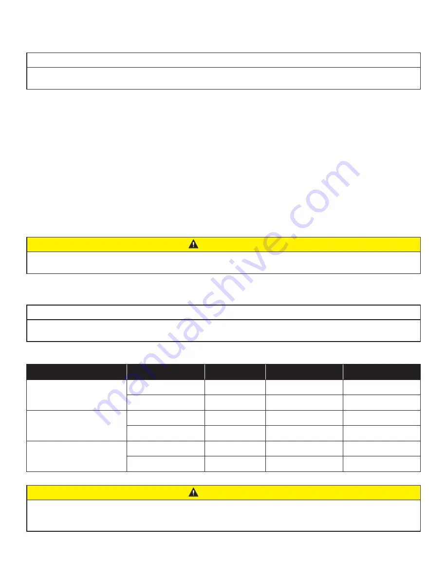
The cooler should be plugged into a fused or breaker-protected circuit. Refer to the table for circuit size
requirements. Cold Front 500 models cannot be connected to a GFCI outlet.
Amperage and Circuit Requirements
Model
Volts +/- 10%
Frequency
Min. Circuit Size
Running Amps
Cold Front 300
120 V
60 Hz
15 A
4.1 A
220/230 V
50/60 Hz
10 A
1.8 A
Cold Front 400
120 V
60 Hz
15 A
8.0 A
220/230 V
50/60 Hz
10 A
5.0 A
Cold Front 500
120 V
60 Hz
25 A
16.5 A
220/230 V
50/60 Hz
15 A
8.6 A
CAUTION
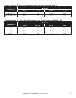
Do not exceed the amperage ratings of the extension cord. Undersized extension cords create excessive
drops in voltage, causing the electric motor to generate excess heat. This results in inefficient motor
operation and premature motor failure and will void the warranty.

