WWW.BIGASSFANS.COM © 2021 DELTA T LLC ALL RIGHTS RESERVED.
18
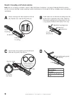
Step 6.3 Coupling and Tube Assembly
Note:
Prior to coupling installation, review “Step 6.5 Swirler Installation” on page 21. Model IRH 125 requires
swirler tab to be installed under coupling. Swirler installation for this model must be complete prior to coupling
installation.
A
B
C
D
Close coupling and slide opposite end into
tab. Position tab underneath guide rail.
Insert wide end of slide bar/coupling lock into
guide rail on opposite end of tabs. Slide the
slide bar/coupling lock up the guide rail until
snug (approximately 3" [8 cm] to 4" [10 cm]).
Insert tubes into coupling until end of each
tube rests against internal pins.
Description
Coupling
Slide Bar/Coupling Lock
Tube
Open
Coupling
Guide Rail
Closed
Coupling
Tab
3" to 4"
(8 to 10 cm)
Slide Bar/Coupling Lock
Wide End
Guide Rail
Internal
Pins
Tube
Tube
Coupling
End View
Align coupling so that
slide bar/coupling lock
is rotated to the 2:00 or
10:00 position.
Slide Bar/Coupling Lock
Coupling
Tube
Summary of Contents for IRH
Page 4: ......

