WWW.BIGASSFANS.COM © 2021 DELTA T LLC ALL RIGHTS RESERVED.
21
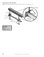
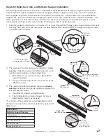
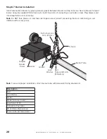
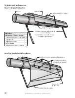
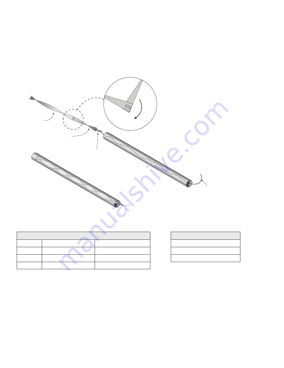
Step 6.5 Swirler Installation
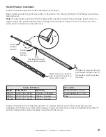
Swirler installation required for models specified in chart below.
Begin installing swirler at end of tube section as described in the “Swirler Installation” chart below and continue
towards burner.
Note:
If heater length is extended 10 ft (3 m) beyond the specified minimum heat exchanger length, swirler can
begin in either the specified tube section (according to the “Swirler Installation” chart) or the end of the 10 ft
(3 m) extension and continue towards burner.
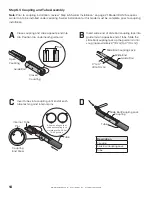
Swirlers should not to be installed through 180° “U” sections. For this reason, 15 ft and 20 ft long swirler
packages each contain two swirler starter sections to allow for starter pieces to be installed before and after “U”
sections. Swirler starter section identified as section with tab on end.
Swirler Installation
Model
Tube Section
Swirler Qty
IRH 125
3rd 10 ft (3 m) Section
2 St 2 Adapters
IRH 150
4th 10 ft (3 m) Section
1 S 1 Adapter
IRH 200
5th 10 ft (3 m) Section
1 S 1 Adapter
Description
Swirler Starter 62 in. (1.6 m)
Swirler Adapter 62 in. (1.6 m)
Tube
Twist
Swirler
Adapter
Section
Swirler
Starter
Section
Tab
(Tab located only on
swirler starter section)
Fold tab around outside of
tube nearest to the vent to
hold swirler in place.
Installer can use pull string to
pull swirlers through tube, or
the swirlers may be pushed
into tube.
Summary of Contents for IRH
Page 4: ......


