background image


Operating manual No. 

057-2-6-0008-R0


Page 14 

Version 2018


EN 

3


 Safety section 


3.1


Environmental working values 

The use environment of the machine must be well lit, must not present explosion hazards of any 
kind and must be protected from atmospheric precipitations. 
The machine works properly within the following values: 


Ambient temperature between 5° and 40° C; 


Ambient humidity between 30% and 90% without condensation. 

 
STORAGE:  if  the  machine  has  been  unpacked,  store  it  in  a  closed  space  protected  from  bad 
weather conditions. 
 

3.2


Sound level 

During the normal conditions of use some measurements were made at the workplace and around 
the machine at a distance of 1 m and at 1.6 m height above the ground. 
The survey was carried out with a sound level meter, complying with IEC 651 standard, class 1 and 
the  result  of  the  assessment  was  lower  than  the  minimum  limit  of  action  required  by  the 
regulations in force. 
 

3.3


Residual risks 


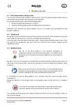
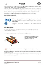
The  use  of  the  lifting  platform  is  the  absolute  prerogative  of 
professional operators and specialized technicians, in compliance with 
the requirements of Machinery Directive 2006/42/ EC and subsequent 
updates. 


Operators must be in full possession of all physical and mental abilities during the performance of 
their tasks on the machine; they must not, for example, be under the influence of sedatives, drugs 
or alcohol. 


Before carrying out the work, the Operators must be perfectly aware of 
the  position  and  operation  of  all  the  controls  and  specifications  of  the 
machine indicated in the "EC Use and Maintenance Manual". 

 
It  is  forbidden  to  use  the  lifting  platform  for  a  purpose  other  than  those  provided  by  the 
manufacturer. 
Always  pay  attention  to  the  danger  and/or  warning  signs  placed  on  the  machine  or  in  adjacent 
areas. 


The machine must always be operated by a single Operator who pays 
particular attention to the ascent/descent phases of the machine. 

 
The operators standing areas must always be kept clean and free of any oily residues to allow an 
easy and safe passage. 


Summary of Contents for CFL-500

Page 1: ...and Maintenance Manual Central lifting platform CFL 500 Model Version CFL 500 CUSTOM VERSION CFL 500 Q QUAD ATV VERSION Bike Lift EUROPE s r l via Don Milani 40 42 43012 Sanguinaro di Fontanellato PARMA Italy Website www bikelifteurope it E mail info bikelifteurope it ...

Page 2: ...1 Machine name 10 2 2 Machine identification 10 2 3 Machine description 11 2 4 Intended use and reasonably foreseeable misuse 12 2 5 Technical specifications 13 2 5 1 CFL 500 13 2 5 2 CFL 500 Q 13 3 Safety section 14 3 1 Environmental working values 14 3 2 Sound level 14 3 3 Residual risks 14 3 4 Operator protections 15 3 5 Safety systems 15 3 6 Pictograms 16 4 Transport and handling section 17 4 ...

Page 3: ... 20 6 3 Scrapping 20 7 Operation section 21 7 1 Loading operations 21 7 2 Unloading operations 22 8 Maintenance section 23 8 1 Lubrication 23 8 2 Jack replacement 23 8 3 Cleaning 24 8 3 1 Initial cleaning 24 8 3 2 General cleaning of the machine 24 8 3 3 Cleaning of the work areas 25 8 4 Problems and remedies 25 8 4 1 FOOT PUMP 26 SPARE 29 ...

Page 4: ...umidity in order not to compromise its durability over time Deliver the Manual to any other user or subsequent owner of the Machine Workers in charge of using this machine must have all the necessary information and must receive proper training The manual and relative documentation are confidential by law with the prohibition of reproduction or transmission to third parties without receiving the e...

Page 5: ...r written authorization of the manufacturer 1 3 Warranty Bike Lift Europe S r l will not be held responsible for inconveniences breakages accidents etc due to lack of knowledge or failure to apply the procedures specified in this Manual The same applies to the execution of modifications changes or for the installation of accessories not previously authorized 1 3 1 Warranty conditions Bike Lift Eur...

Page 6: ...recommended to specify exactly the following data Model and serial number of the machine Code number and part name Required quantity Shipping means address and telephone number For replacements use only genuine spare parts Do not wait until the components are completely worn before replacing them CAUTION THE RECIPIENT WILL BE CHARGED FOR THE REPLACEMENT TOGETHER WITH THE SHIPPING COSTS We recommen...

Page 7: ...FL 500Q Seriennummer Jahr Funktion Heben von Krafträdern für Wartungsarbeiten am Fahrzeug die grundlegenden Sicherheitsanforderungen der folgenden Richtlinie erfüllt 2006 42 EG Maschinenrichtlinie und mit den folgenden harmonisierten Normen übereinstimmt UNI EN ISO 12100 2010 Sicherheit von Maschinen Allgemeine Gestaltungsleitsätze Risikobeurteilung und Risikominderung UNI EN 1493 2010 Fahrzeugheb...

Page 8: ...e EMC 2014 35 EU Low Voltage Directive LVD EN ISO 12100 2010 Safety of machinery General principles of design Risk assessment and risk reduction UNI EN 349 1993 A1 2008 Safety of machinery Minimum spaces to avoid the crushing of body parts EN 1493 2010 European standard on vehicle lifting platforms EN 982 2009 Safety of machinery Safety requirements related to systems and their components for hydr...

Page 9: ... Yellow triangle pictogram generally indicates a Warning Risk e g risk of high temperatures risk of crushing the hands BLUE round pictogram generally indicates an Obligation for example the obligation to wear certain PPE goggles or the Obligation to read the User Manual Round red Prohibition pictogram indicates in general a Prohibition for example person access prohibition prohibition of hand acce...

Page 10: ...ication data of the machine are indicated on the plate placed on the structure and shown in the attached declaration of conformity Refer to these details for ordering spare parts and for any kind of contact with the manufacturer It is absolutely forbidden for the user to remove or alter this plate Any modification or removal of the plate will void any warranty The machines can be subject to update...

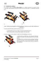
Page 11: ...ads and ATVs The basic parts of the lifting platform see Figure 2 are An orange lifting structure through a load and unload pedal system A base equipped with 2 braking wheels black and 2 free wheels The fall protection system shown in yellow in the following figure consists of a mobile anchoring toothed bar on the base with automatic coupling that prevents the accidental descent of the mobile surf...

Page 12: ...r the mechanical part and for the bodywork Any other use different from the one indicated is to be considered as not planned and may cause damage to the machine and Operators It is therefore FORBIDDEN The machine must always be operated by only one Operator The Operator must always work in proper lighting conditions and wear clothes and protections appropriate to the task performed typical activit...

Page 13: ...Maximum bearing 500 kg Maximum height 45 cm Minimum height 8 cm Safety positions number 3 Length 41 cm Width 38 cm Pedal operation Weight 30 kg 2 5 2 CFL 500 Q see exploded diagram attached to this manual VERTICAL SCISSOR LIFTING PLATFORM PARAMETER VALUE Maximum bearing 500 kg Maximum height 55 cm Minimum height 18 cm Safety positions number 3 Length 41 cm Width 38 cm Pedal operation Weight 30 kg ...

Page 14: ...s in force 3 3 Residual risks The use of the lifting platform is the absolute prerogative of professional operators and specialized technicians in compliance with the requirements of Machinery Directive 2006 42 EC and subsequent updates Operators must be in full possession of all physical and mental abilities during the performance of their tasks on the machine they must not for example be under t...

Page 15: ... platform the operator must wear appropriate personal protective equipment PPE such as gloves and safety footwear Always wear work clothing normally used in the mechanical workshop activity 3 5 Safety systems The central lifting platform see Figure 2 consists of a lifting structure through a hydraulic pedal system for loading and unloading The fall protection system shown in red in the following f...

Page 16: ...rm Use it only to lift objects Do not modify the lifting platform The load must always remain firm and stable 3 6 Pictograms Danger of crushing hands with the lifting platform arms When the platform is at the desired height insert the locking bar to prevent it from falling down accidentally Load the vehicle only when the platform is completely lowered Before lifting it make sure that nothing is su...

Page 17: ...ng the journey it is possible to be deteriorated or damaged Upon receipt of the machine immediately check if the packages are clearly damaged If so accept the goods with reserve by making photographic evidence of any damage Open the box by cutting the clips and the closing adhesive tape Make sure all the material shown on the delivery note is actually present Make sure the parts of the machine hav...

Page 18: ...r other possible boundaries boundaries are imaginary lines that delimit the work or safety areas of other machines or structures WARNING It is absolutely forbidden to position the lifting platform on bumpy or inclined ground 1 Remove all components from the box taking care not to lose any piece and place the structure of the kickstand on a work surface at a suitable height 2 Lift the structure man...

Page 19: ...d to the reversed U shaped crosspiece Figure 6 Figure 6 5 Once the stem has been inserted continue to lift for a few centimeters release the mechanical safety kickstand and lower the kickstand to the rest position Figure 7 6 Loosen the two door knobs on the base of CFL 500 and insert the two wheels Once the desired width is set tighten the knobs to lock the wheels position At this point the motor ...

Page 20: ...ove all moving parts by proceeding to the opposite of what is described in the Installation chapter For the lifting modes and the relative specific safety precautions refer to the Transport Handling and Storage chapter 6 3 Scrapping The dismantling operations of the machine must be carried out in total safety by using the protections At the end of the machine s life it is necessary to proceed to t...

Page 21: ...istance from the lifting platform according to the length allowed by the control panel cable Proceed with the lifting operation by pressing the foot pedal repeatedly making it move alternately from top to bottom to generate hydraulic pressure By stopping the action on the pedal the pump will stop but will remain under pressure Once the working height has been reached slightly lower the lifting pla...

Page 22: ...ar lodging are not obstructed by foreign bodies 2 Use the pump to raise the lifting platform with about 3 cm then release the safety bar Figure 5 4 through the appropriate descent control pedal 3 When the descent is complete remove the lifting platform Read carefully the attached use and maintenance manual jack ...

Page 23: ...e machine to make sure that the structures are not deformed or cracked Check the welding and the proper functioning of the safety devices Make sure the machine ascends and descends smoothly If necessary add hydraulic oil to the pump by using the special level plug Use MOTOREX COREX HLF D 32 hydraulic oil or equivalents 8 1 Lubrication Lubricate the pins and moving parts at least once a month In ca...

Page 24: ...ds and consumables used in the appropriate landfills according to the legislation of the Country The cleaning of the lifting platform can be carried out by personnel without specific technical skills who however know the main characteristics of the machine in order to avoid dangerous situations 8 3 2 General cleaning of the machine Perform the general cleaning of the machine weekly with the utmost...

Page 25: ...se suitable vacuum cleaners and proper equipment 8 4 Problems and remedies The most common problems encountered during the work the probable causes that determine them and the possible remedies to be taken to eliminate them are listed below When implementing the suggested remedy always follow the instructions described in the Instructions to which the remedy refers Bike Lift Europe s r l will solv...

Page 26: ...nufacturer Oil level too low Check the oil level Figure 6 and fill it up if necessary The pump does not reach maximum pressure Maximum pressure valve improperly calibrated for the models where it is present Contact the manufacturer Oil leak in the hydraulic system Check the leak in the system and repair it The pump goes under pressure but the load does not move Excessive load Reduce the load The o...

Page 27: ...er The piston does not return Oil supply line throttled or plug improperly connected Check the oil supply line If the return is due to gravity possible lack of load on the cylinder Load the cylinder Cylinder spring broken Check and repair the cylinder Cylinder release valve not working Check and repair the cylinder Internal pump failure Check the leak in the pump and contact the manufacturer The p...

Page 28: ...Operating manual No 057 2 6 0008 R0 Page 28 Version 2018 EN Figure 6 JACK ...

Page 29: ...Operating manual No 057 2 6 0008 R0 Page 29 Version 2018 EN SPARE PARTS TECHNICAL DRAWINGS jack ...

Reviews: