background image


71 

DS440IS 


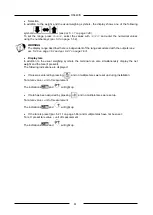
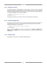
 prints out the selected total 


SUMMAR 

total print of a group of codes 


RESET 

resets the selected total 


CODE 

selects the code 


LIST 

displays the list of totals 

 
Within  the 

LIST 

  menu,  you  can  select 

SUMMAR 

RESET

CODE 

(with  the  functions  explained 

above) and 

ENTER 

, which displays the individual selected total. 


6.2.17  User menu access 


This function allows you to use a password to protect the access to the user menu. 
Two situations may occur: 


The security password has been set, thus the protection device is activated. To access the user 
menu, press the 

MENU 

shortcut key and digitize the same verification password as the security 

password. 


The  security  password  has  not  been  set  (initial  situation  =  0).  The  protection  device  is  not 
activated. 


Set the password by following pathway: 


...>MENU>Access to user menu 
 

Once the password has been set, the protection device will be activated, thus the password must be 
digitized again for each successive access to the user menu. 


6.2.18  Weighing operation 


This  function  allows  you  to  disable-enable  the  printout  during  the  weighing  operation.  It  may  be  of 
use if the operator only wishes to use the printer for printing the totals. 


Summary of Contents for PS440 Series

Page 1: ...Terminal D440IS and power supplier PS440 xxx PS440 A xxx USE AND MAINTENANCE MANUAL Manual code n 81320122 Edition 05 11 2018 ...

Page 2: ......

Page 3: ...A xxx 22 3 2 2 D440IS 22 3 2 4 12x0 35 mm power supplier terminal connection cable 23 3 2 5 6x0 5 mm cable for the cells inputs outputs analogue output 23 3 2 6 Optical fibre 23 3 3 Sizing the system 24 3 3 1 PS440 xxx D440IS connection 24 3 3 2 Connection of the D440IS scale Load cells type Eurocell IS xxx 24 3 3 3 Connection of D440IS clean contact inputs 24 3 3 4 Connection of PS440 xxx Clean c...

Page 4: ...et tare list 68 6 2 13 Progressive number 69 6 2 14 Coefficient Management 69 6 2 15 Extraction data 69 6 2 16 Totals management 70 6 2 17 User menu access 71 6 2 18 Weighing operation 71 6 3 Printing weighing data 72 6 3 1 Weighing data reprint 73 6 3 2 Automatic print out 73 6 4 Operating modes 74 6 5 Standard operation 74 6 6 Loading extraction operation 74 6 7 Unloading extraction operation 75...

Page 5: ...2 Point to point mode 96 7 2 3 Optic loop mode 96 7 2 4 Optical fibre adapter RS232 FO 232 97 7 3 Printers 98 7 3 1 Connection with STB60 in the RS232 mode 98 7 3 2 Connection to STB112 in RS232 TM295 TMU295 LX300 ITALORA 99 7 4 Connection to a PC 100 7 5 4 20 mA analogue output 101 8 MAINTENANCE 104 8 1 Lithium battery 104 8 2 Casings 104 8 3 Test of the system 104 9 TROUBLESHOOTING 106 9 1 Malfu...

Page 6: ...6 DS440IS WARNING Document relating to CESI 00 ATEX 038 CESI 05 ATEX 022 X and CESI 05 ATEX 023 certificates No changes are permitted without the approval of the Authorised Person ...

Page 7: ...ately invalidated and the Manufacturer may not be held liable for any damage to people or property The alteration or removal of the data plates and seals is strictly prohibited as a consequence make sure that all plates and labels are readable and on the contrary contact the After Sales Office The manufacturer shall not be liable for any damages caused by incorrect handling of the terminal The inf...

Page 8: ... to observe the instructions will result in death or serious injury CAUTION Denotes an operation or procedure where failure to observe the instructions could result in minor injury or damage to the instrument WARNING Information or instructions on how the system is to be operated correctly in order to maximise its service life or prevent loss or damage of programmed data or to optimise operation w...

Page 9: ...y explosive gas or dust This zone is also called SAFE ZONE Text and messages displayed on the terminal are printed in this manual using special characters Messages Display messages appear like this Menu pathways 2 F OTHER MENU Contrast The character indicates the transition from one menu option to the next 1 4 Documentation Use and maintenance manual the manual you are reading CD ROM contains info...

Page 10: ... extremely easy to use has facilities for changing the shape and size of the display characters to suit various conditions of use The terminal provides a wide range functions which combined with the possibilities for expansion allow for easy interfacing with external equipment Certain of the standard characteristics of the system are listed below installation in ZONES 1 2 21 22 3 metre terminal po...

Page 11: ... supply 24 VAC low voltage power supply 1 6 2 Options 2 serial outputs in optical fibre 4 20 mA analogue output WARNING The 2 options serial outputs and analogue outputs are alternatives MPP memory expansion Terminal power supplier connection cable to customer s specifications max 10 m Single wall support for terminal and power supplier ...

Page 12: ...ue cells up to four 350 Ohm analogue cells Minimum impedance 87 5 ohm Analogue load cell power by means of MAX 6V zener barrier Internal resolution 500000 points Resolution in type approved version up to 4000 divisions Maximum input signal 23 mV Sensitivity 0 63 uV division Full scale stability 5 ppm C Zero stability 5 ppm C Compensated temperature range 10 40 C Operating range 10 55 C Protection ...

Page 13: ...pplier Version with very low safety voltage 24 VAC 10 15 50 60 Hz Pn 20 VA On Exe terminals Output contacts on Exi terminals Vmax 125 VAC DC Imax 200 mA 1 7 3 Power supplier PS440 A xxx PS440 A 230 VAC power supply Standard version 230 VAC 10 15 50 60 Hz Pn 20 VA On Exe terminals PS440 A 115 VAC power supplier 115 VAC version 115 VAC 10 15 50 60 Hz Pn 20 VA On Exe terminals Output contacts on Exi ...

Page 14: ...14 DS440IS 1 8 Dimensions and weight of the terminal Weight 4 kg The dimensions are given in mm Figure 1 1 Dimensions and weight of the wall mounted terminal version ...

Page 15: ...15 DS440IS Weight 4 kg The dimensions are given in mm Figure 1 2 Dimensions and weight of table top version ...

Page 16: ...16 DS440IS Weight 9 kg The dimensions are given in mm Figure 1 3 Overall dimensions and weight of the terminal and power supplier on a single wall support ...

Page 17: ...tact the manufacturer or your nearest Service Centre To enable us to deal with your request swiftly always quote the serial number of your terminal which can be found on the seal label Also provide information about the system in which the terminal is installed 1 10 Warranty The conditions of warranty are stipulated in the contract of sale ...

Page 18: ...ns The operating conditions for the electronic terminal are subject to the regulations in force in the country in which the terminal is used All use of the terminal in conditions which do not comply with these regulations is prohibited 2 3 Recommendations for installation 2 3 1 Classification of zones and substances The terminal power supplier load cells connection cable system must be approved fo...

Page 19: ... II 2 3 4 Categories of equipment The appliances are classified in categories depending on their safety 1 2 3 There is also a breakdown in equipment for the presence of dust D Dust and gas G Gas Danger zone Categories under Directive ATEX 2014 34 UE Equipment Protection Level Gas mist or vapours Zone 0 1G Ga Gas mist or vapours Zone 1 1G or 2G Ga or Gb Gas mist or vapours Zone 2 1G 2G or 3G Ga Gb ...

Page 20: ...tible with the dust ignition temperature 2 3 7 Description of the system installed To facilitate the installation operations and make it easier to check whether the electrical and mechanical parameters of the various parts forming the system are compatible with the surrounding conditions presence of gas and dust the Manufacturer provides certain typical systems as described below The components of...

Page 21: ...st be periodically inspected and cleaned Make sure that the terminal is connected to an electrical outlet socket equipped with an efficient earth connection Make sure that the line complies with the applicable regulations Check that there is no difference in potential between the earth and neutral conductors If the terminal is to be connected to other devices e g a computer or other these devices ...

Page 22: ...TEX 023 II 2 1 G Ex e mb ia Ga IIC T5 T4 Gb II 2 1 D Ex tb mb ia Da IIIC T100 C T135 C Db Tamb 20 C 40 C T5 T100 C Tamb 20 C 55 C T4 T135 C 3 2 2 D440IS Certified CESI 05 ATEX 022 X Marking CESI 05 ATEX022 X II 1 G Ex ia IIC T5 Ga II 1 D Ex ia IIIC T100 C Da IP54 Tamb 20 C 55 C T5 T100 C 3 2 3 Eurocell series IS xxx analogue cells Certified CESI 00 ATEX 038 Marking CESI 00 ATEX 038 II 1 G Ex ia II...

Page 23: ...cable m 1 5µH m Insulation voltage 1000V Screened cable 3 2 5 6x0 5 mm cable for the cells inputs outputs analogue output Ccable 250pF m Lcable 0 95µH m Insulation voltage 1000V Screened cable 3 2 6 Optical fibre 200 µm HCD for sections of up to 500m Mod TR60 Fort Fibre RS232 transmitter ...

Page 24: ...PS440 xxx Clean contact outputs towards safe zone The length of this route depends on the characteristics of the barriers used by the customer For example with an MTL707 Exi circuit Maximum length 200 m 3 3 5 Connection of PS440 Axxx Output Exi Using Atex parameters of Exi outputs the device can be connected in ATEX marked danger zones with Exi protection method e g low current ATEX solenoid valve...

Page 25: ...on characteristics of the system 3 4 1 For ambient temperatures of up to 40 C Protection modes Ex e m ia Gas group IIC Gas temperature category T4 Protection degree IP54 Maximum surface temperature of casing 100 C Operating ambient temperature 20 C Tamb 40 C 3 4 2 For ambient temperatures of up to 55 C Protection modes Ex e m ia Gas group IIC Gas temperature category T4 Protection degree IP54 Maxi...

Page 26: ...with external sheath diameter ranging from 5 to 10 mm Channel 1 optical fibre input COM1 exi 4 20mA analogue output 4 4 Access 4 PG11 cable clamp suitable for cables with external sheath diameter ranging from 5 to 10 mm Channel 2 optical fibre input COM2 5 Access 5 closed by a cap do not use 6 Access 6 PG9 cable clamp suitable for cables with an outer sheath diameter ranging from 4 to 8 mm Exi sca...

Page 27: ...ty power output towards D440IS exi 4 20mA analogue output Figure 4 2 PS440 xxx power supplier accesses 4 1 32 PS440 A xxx power supplier accesses Key 1 M16x1 5 Black cable clamp suitable for cables with external sheath diameter from 5 to 10 mm Mains power input 2 M16 1 5 Black cable clamp suitable for cables with external sheath diameter from 5 to 10 mm Output cable input 3 M16 1 5 Blue cable clam...

Page 28: ... your maintenance personnel or contact our Assistance Service directly For the correct connection of the terminal to the electrical supply line proceed as follows install in the absence of gas or combustible dust connect the power cable 3x1 5 mm by means of the cable clamp in power supplier PS440 xxx PS440 A xxx strip the internal conductors and insert them into the exe terminals by means of cable...

Page 29: ...ion against heating The socket must be equipped with a disconnector Key 1 Bipolar knife switch at the customer s care 2 Power cable at the customer s care L N T 3 Power input access PS440 xxx PS440 A xxx 4 Exi D440IS power cable 5 6 mm cable ground earth connection at the customer s care Figure 4 3 Terminal connection to the electricity main ...

Page 30: ...indicating the version of the power supplier and applicable voltage Figure 4 4 View of internal terminals for connecting power supply to PS440 xxx CAUTION Maximum use conditions PS440 230 230 VAC 10 15 PS440 115 115 VAC 10 15 PS440 24 24 VAC 10 15 Maximum power input 20 W Power cable with three 1 5 mm section conductors and 10 mm maximum external diameter ...

Page 31: ...ating the version of the power supplier and applicable voltage Figure 4 4 a View of internal terminals for connecting power supply to PS440 A xxx CAUTION Maximum use conditions PS440 A 230 230 VAC 10 15 PS440 A 115 115 VAC 10 15 PS440 A 24 24 VAC 10 15 Maximum power input 20 W Power cable with three 1 5 mm section conductors and 10 mm maximum external diameter ...

Page 32: ...le clamp and connected to the chassis 2 Exi output Insulated shielding braid 3 Double conductor 4 12x0 35 mm screened cable 5 JALIM terminal boards on D440IS 6 JOUT CPU terminal boards on D440IS 7 Terminals 9 19 on PS440 A xxx Figure 4 5 PS440 xxx connection to D440IS ...

Page 33: ... clamp and connected to the chassis 2 Exi output Insulated shielding braid 3 Double conductor 4 12x0 35 mm screened cable 5 JALIM terminal boards on D440IS 6 JOUT CPU terminal boards on D440IS 7 Terminals 9 19 on PS440 A xxx Figure 4 5 a PS440 A xxx connection to D440IS ...

Page 34: ...nal make sure that there is no potentially explosive gas or dust turn off the terminal by means of the knife switch wait 1 minute for the internal capacity to completely discharge unscrew the 4 screws at the rear 1 turn the rear panel downwards access the terminals as indicated in Figure 4 7 on page 1 35 and in Figure 4 8 on page 1 36 Key 1 Screws for securing rear panel in place Figure 4 6 Openin...

Page 35: ...otection degree of the casing will be impaired if the seal is positioned incorrectly DANGER Take care of the ground connection soldered between the front and rear casing when removing the upper cover Re solder if necessary The ground connection prevents electrostatic charges from building up on the surface of the terminal ...

Page 36: ...36 DS440IS Key 1 Optional connectors 2 Ground connections Figure 4 7 Opening the terminal and view of the internal parts ...

Page 37: ...nnections Key 1 JALIM Exi power input from PS440 xxx PS440 A xxx 2 JOUT_CPU Command output towards PS440 xxx PS440 A xxx 3 JINPUT_EXI Exi input 4 JCELL Exi scale input 5 Protective scale input cover Figure 4 8 Internal terminal connections ...

Page 38: ...on so as to earth the screen as indicated in the following figures Strip the cable Leave the cable screen free 1 Insert the cable into the top of the cable clamp 2 and plastic insert 3 Turn the cable screen around the O Ring 4 Make sure that the cable screen exceeds the O Ring by 2 mm 4 Fit everything into the wall mounted unit 5 Tighten the top of the cable clamp 2 DANGER To prevent uncontrolled ...

Page 39: ...nector of which must be inserted into the 6 pin terminals JCELL point 4 of Figure 4 8 on page 1 36 after having removed the protective scale input cover point 5 of Figure 4 8 on page 1 36 WARNING The cable screen must always be earthed as explained in par 4 4 on page 1 37 Do not route the connection cable to the weighing platform together with non exi cables i e those without intrinsic safety ...

Page 40: ...low TERMINAL JCELL Pin Jcell connector Description 1 SIG Signal 2 SIG Signal 3 EX _EX Power supply 4 EX _EX Power supply 5 SENSE Sense 6 SENSE Sense WARNING After the cables from the weighing platform have been connected restore the metric seals see point 6 of Figure 4 8 on page 1 36 by fitting the protective cover back in its correct position ...

Page 41: ...ey 1 Terminal board of power supplier PS440 A xxx Figure 4 9 Output connection CAUTION Technical specifications Output Mechanical voltage free contact Maximum switchable voltage 125 VAC DC Maximum switchable current 200 mA I O refresh time 1 10 s DANGER When the weighing system is installed in complex plants that can represent a danger hazard for operators enlist the assistance of specialised pers...

Page 42: ...ATEX Uo 13 4V I or 79th Po 0 32W Maximum operating voltage 12 VDC Maximum operating current 50 mA Refresh time I O 1 10 s DANGER When the weighing system is installed in complex plants that can represent a danger hazard for operators enlist the assistance of specialised personnel to perform several manoeuvres without load in order to acquire the experience necessary to work in safety ...

Page 43: ...the rear of the indicator point 3 Figure 4 8 on page 1 36 The wiring diagram is given in Figure 4 10 on page 1 42 Key Pi Part inside terminal Pe Part outside terminal Figure 4 10 JINPUT_EXI terminal board for Input Output connections CAUTION Technical specifications Mechanical voltage free contact I O refresh time 1 10 s ...

Page 44: ...ystem is installed in complex plants that can represent a danger hazard for operators enlist the assistance of specialised personnel to perform several manoeuvres without load in order to acquire the experience necessary to work in safety ...

Page 45: ...e with the groups of substances in the zone Is the maximum ambient temperature compatible with the maximum operating temperatures of the components used Is the surface temperature of the components compatible with the dangerous substances present Have the data plate specifications been checked in relation to the power supplied to the components In particular rated voltage Un must correspond to the...

Page 46: ... to the terminal boards are made with pins and that there are no copper wires that could reduce the distance of the circuits in air The cable clamps must be adequately tightened Unused cable clamps must be plugged Make sure that the casings are closed with the supplied screws and that the seals are well seated Make sure that D440IS has been grounded with the yellow green cable and safety screw Mak...

Page 47: ...bing the system only if it is installed by Coop Bilanciai An operation and maintenance manual for the terminal power supplier the manual you are now reading The safety instructions of terminal D440IS The safety instructions of power supplier PS440 xxx PS440 A xxx The safety instructions of the load cells and junction box ...

Page 48: ...ghing function keys 2 Display of weight and additional information 3 Alphanumeric keys Figure 5 1 Front of terminal The LCD Liquid Crystal Display point 2 Figure 5 1 on page 1 47 in addition to the universally recognised weighing symbols also displays information in extended format related to the operation of the terminal ...

Page 49: ...near to zero i e within 1 4 1 4 of a division Tare symbol Indicates the presence in memory of an acquired tare value Preset tare symbol Indicates that a tare value has been entered from the keypad Gross weight symbol Gross weight symbol with units of measurement in lb as alternative to B This symbol only illuminates when the unit of measurement is lb pounds Minimum weighment Net weight symbol Weig...

Page 50: ...50 DS440IS 5 1 1 Selection display symbols Weight indication Below preset lower limit Weight indication Within the preset upper and lower limits Weight indication Above the preset upper limit ...

Page 51: ...cancel tare On pressing this key the weight on the scale is acquired as the tare value provided the following conditions are satisfied the weight must be stable the weight must have a positive value the weight must not exceed the maximum capacity The symbols and will light up on the display On MD terminals the weight indication will be displayed using the division of the lower range On ME terminal...

Page 52: ... weight will be displayed using the division of the range within which the net weight value falls while on ME terminals the net weight division shall be that of the range within which the gross weight falls On MD terminals the maximum preset tare value is limited to the maximum capacity of the first weighing extension indicated on the metrological data plate Print and or send Allows a weighing opt...

Page 53: ... page 1 47 Keys for entering numeric values and alphanumeric characters Key for entering decimal digits Use this key for entering decimal values Enter or confirm Press to confirm an operation WARNING The functions of the keys may vary and are indicated on the display ...

Page 54: ...e ground earth connection at the customer s care Figure 5 2 Terminal connection to the electricity main DANGER Make sure that the protective casing is in a perfect condition before powering the terminal Remove any dust from the casings of both the terminal and power supplier Identify the main switch that disconnects the entire panel from the power supply To identify this switch contact your intern...

Page 55: ...indication to appear terminals subject to metrological verification only If on completion of the operation the display shows a value other than zero press to zero set the reading If the display is not zero set on pressing the key check that the platform scale is in fact unloaded If not unload the scale switch off the terminal and then switch it on again If the problem persists contact your Service...

Page 56: ...n OTHERS you can switch to other functions managed by the terminal The arrow keys allow you to move respectively up down right and left By pressing SELECT you can select the required option or enter a submenu The keys and allow you to change the way the menu pathway is displayed extended pathway pathway expressed numerically Selecting ESC returns you to the previous menu level By pressing ESC repe...

Page 57: ...anumeric data Alphanumeric data may be entered as follows Select a function for which an alphanumeric value may be entered e g the generic code press the keys corresponding to the letters you want to enter press to confirm Bear in mind that pressing the same key repeatedly displays each of the letters the number and the special characters associated with that key in sequence to confirm the letter ...

Page 58: ...s displayed in reverse video Confirm the selection by pressing OK To toggle between upper and lower case letters press the key in correspondence with the indication CAPIT SMALL Below is a list of the characters associated with each key Alphanumeric keys Characters 0 blank 1 ª º A B C 2 â ä à å Ä Å ç Ç D E F 3 è ê ë è È æ Æ G H I 4 ï î ì í J K L 5 M N O 6 ô ö ò ó Ö ñ Ñ P Q R S 7 ß T U V 8 ü û ù ú Ü...

Page 59: ...reviations that appear on the display may be customised during installation For this reason the abbreviations related to the shortcut keys that appear in brackets alongside or below the pathways described in the following paragraphs may have been modified by the installer Ask your installer for a list of the abbreviations and their meanings The pathways themselves may also vary according to the nu...

Page 60: ...ate Time Shortcut key DATIME To change quickly from summer to winter time press or 1 hour alternatively use the option CHANGE 6 2 3 Weight display You can change the way the weight value is displayed on the terminal To select the display mode follow the pathway MENU Display Shortcut key VISUAL The possible display modes are 15mm digits The display shows the gross weight or net and the weighing sym...

Page 61: ...Display tare In addition to the usual weighing symbols the terminal can also simultaneously display the net weight and the tare if present The following indications are displayed If tare was entered by pressing and no multiple tares were set up during installation Tare tare value unit of measurement The indications and will light up If tare has been acquired by pressing and no multiple tares were ...

Page 62: ...rement Tare 2 PT preset tare 2 value unit of measurement Or Tare PT non coded tare value unit of measurement Tare 1 PT preset tare 1 value unit of measurement Tare 2 PT preset tare 2 value unit of measurement The indications and will light up NOTE Tare 1 and Tare 2 may also be recalled via numeric code par 6 2 11 on page 1 66 Extraction This type of display can only be obtained if the extraction o...

Page 63: ... the terminal cannot be operated Do not switch off the terminal during this operation as this could result in the loss of the data in memory 6 2 5 Reprint See par 6 3 1 on page 1 72 6 2 6 Setting the outputs as Setpoints if enabled The two available outputs may be used in setpoint mode In this way the output is activated when the weight reaches the set value MENU Data management Set Point Shortcut...

Page 64: ...an alphanumeric code with a maximum of 8 characters that can be printed and or transmitted The maximum of codes that can be entered varies according to the other types of data managed To enter a generic code follow the pathway MENU Data management Code management Generic code Shortcut key CGEN Enter the alphanumeric code as described in par 6 1 3 on page 1 56 If the value of the generic code empty...

Page 65: ...ing mode The product code is a numeric code of up to 6 digits while the alphanumerical description can contain up to 20 characters The maximum number of codes that can be entered is defined during the installation phase It varies and depends on which other data must be handled To enter the product code follow the pathway MENU Data Management Code Management Product c List PRODC shortcut key Enter ...

Page 66: ...to cancel the highlighted product code The element is eliminated from the list but remains activated as general data item ESC is used to quit the list produces a printout of a group of codes entered If the field of a tare code is highlighted press the key to confirm the entered code and quit the list If another field is highlighted the one with the description associated with the code for example ...

Page 67: ...ta management Preset tare Entering Shortcut keys TAREC and TARCn where n 1 2 if multiple tares were set during installation Select the tare type enter the code number and press to confirm If necessary enter the tare value The value TARE 2 can be multiplied by a number designated the Packs number which may be entered from the keypad to obtain a sum tare value e g the sum of the tares of n container...

Page 68: ...ator to cancel the highlighted tare code The element is eliminated from the list but remains activated as general data item ESC is used to quit the list produces a printout of a group of tare codes entered If the field of a tare code is highlighted press the key to confirm the entered code and quit the list However if the highlighted field is the one with the value of the tare associated with the ...

Page 69: ...it will not be incremented and not be printed 6 2 14 Coefficient Management This function can be of use when the unit of measurement needs to be converted For example you can calculate the number of litres if the specific weight and overall weight of a liquid are known Follow the following path to access this menu MENU Data Management Coefficient Management COEF shortcut key Enter the required coe...

Page 70: ...otals for the gross weight if enabled during installation net tare and number of weighing operations independently of any associated codes These data are available by recalling the following functions MENU Totals management General total Shortcut key GENTOT MENU Totals management Partial total Shortcut key PARTOT prints selected value RESET resets the total Totals by code Saves the net weight valu...

Page 71: ...thus the protection device is activated To access the user menu press the MENU shortcut key and digitize the same verification password as the security password The security password has not been set initial situation 0 The protection device is not activated Set the password by following pathway MENU Access to user menu Once the password has been set the protection device will be activated thus th...

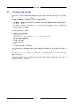
Page 72: ...re is paper in the printer The following data are printed Date and time if enabled Progressive number Product code if selected with the relative alphanumeric description Generic code if selected Gross if enabled Tare s if present Net Coefficient and result if enabled If the relative function is enabled the product code and net weight may be printed in the form of a bar code The printout can be cus...

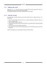
Page 73: ...eight has been obtained Proceed in the following way Enter the weight limit beyond which the print is required modifying the Setpoint01 value see par 6 2 6 on page 1 62 Place the goods to weigh on the scale Print out occurs when the weight value exceeds the one set for Setpoint01 and the stable weight is obtained Unload the scale once the printout has terminated The scale will be ready for another...

Page 74: ...with a number of different components The I O are selected during the installation phase Comply with the instructions in par 6 2 6 on page 1 62 and enter the Set Point 01 and Set Point 02 values Set Point 01 defines the final weight value to extract Set Point 02 gives the weight value that subtracted from the Set Point 01 value marks the change from fast extraction mode to slow extraction mode On ...

Page 75: ...tion The data item is only available if the request output has been envisaged Slow Set Point2 This is the weight that must be extracted at slow speed i e the quantity of material that must be extracted on to the scale at low speed so as to increase the accuracy of the cycle The data item is only available if the slow output has been envisaged Fall This is the quantity of material that still drops ...

Page 76: ...has been enabled Example of how off range is handled Requested quantity 23 5 kg Minus tolerance 0 5 kg Plus tolerance 0 7kg The extracted amount is off range if it is less than the value requested quantity minus tol or more than the value requested quantity plus tol or if it is not within the 23 kg to 24 2 kg range Zero scale tolerance This is the weight within which the scale can consider itself ...

Page 77: ...value is the result of the Extracted total Number of weighing cycles division Minimum extract This is the minimum value extracted in a cycle that is part of the totalized extraction cycles Maximum extract This is the maximum value extracted in a cycle that is part of the totalized extraction cycles Average quadratic deviation sqm This is the value that gives an idea as to how large is the range of...

Page 78: ... start request in the absence of at least one of the above listed conditions If all the above mentioned conditions have been complied with the terminal memorizes the initial weight activates the start ok contact if any starts the extraction process by activating the extraction contacts defined as requested and slow and switches to the extraction page with extraction activated page During the termi...

Page 79: ...ctions available in the current status last line on the display The extraction in progress can always be interrupted from this page with the STOP key Remember that the Stop key shuts down the extraction operation in advance and that during the installation phase the user can decide whether cycles shut down in this way must be printed totalized or rejected Even if cycles shut down with stop must be...

Page 80: ...valid weight has been detected the terminal acquires the extracted weight and checks whether the value is within the tolerance range given by requested quantity minus tolerance and requested quantity plus tolerance The off range output contact is activated if this does NOT occur If automatic printout was enabled during the installation phase the terminal prints the extraction cycle otherwise only ...

Page 81: ...nce a stable weight is obtained the terminal activates the end of extraction output and acquires the extracted weight Supposing that the acquired extracted weight is 26 7 kg The terminal will now proceed to correct the fall value in the following way it calculates the Error or the difference between the acquired extracted weight and the selected requested quantity thus 26 7 23 5 3 2kg it calculate...

Page 82: ...nd the value entered as maximum initial weight is less than the value entered as minimum initial weight The cycle request is annulled Weight off initial range This appears when the user requests an extraction cycle to be started and the gross weight on the scale is not within the initial range i e not between the maximum initial weight and minimum initial weight values 6 9 MPP operation The 4 prev...

Page 83: ...h exit weighing operation Preset weight operations can be done with data recall of 4 numbers for preset weight operations RPD data recall with a vehicle licence plate up to 10 characters for preset weight operations RPD Plate 6 10 1 Entrance and exit weighing Entry Exit Functions require two weighing operations an entry weighing when the weight of the means of transport is taken as first weight an...

Page 84: ...o obtain a print out of the entry weight or first weight enter the required auxiliary data product code client code and vehicle licence plate if such data need to be recorded You are advised to use the shortcut keys PROCOD CLIENT and PLATE and refer to the Use of the Terminal chapter of the user manual to enter the numerical and alphanumerical data Otherwise use these paths MENU Data Management Co...

Page 85: ...ghing operation are held in the memory until the second weight is printed out After this the data are cancelled together with the data recall code The RCD archive can hold up to 300 elements the number of elements can be modified during the installation phase If the terminal has memorised almost the maximum number of RCD codes a message will appear asking for the archive to be resized ...

Page 86: ...ir relative details registered during the entry operation will be displayed The operator can modify these by entering the desired information each piece of information is confirmed by pressing Press ESC The weight on the balance will again be visualised with the RCD code and the entry weight Press key to start the exit weighing operation To cancel the operation press key 2 F before Remember that o...

Page 87: ...ht and net weight If the weighing operation finishes correctly the requested totals are added up the next consecutive number is used and the RCD code and its relative data are cancelled 6 11 3 Unused RCD code recovery The following procedure enables the entry operations again when second weighing procedures cannot be accomplished access the list of RCD codes using the path below MENU Data Manageme...

Page 88: ...the first weighing is associated with the licence plate of the vehicle on entry The card need not be printed in since the first weighing data can be recalled by setting the vehicle licence plate again when this reaches the exit The procedure can be configured in both modes during the installation phase with data print out with data memorising The selected mode will appear on the display when the m...

Page 89: ...e and is valid only for a single operation The recognition code used during these procedures can be a data recall code RPD of up to 4 figures or the vehicle licence plate code RPD Plate of up to 10 alphanumerical characters decided during the installation phase 6 13 1 How to make the list of preset weights As indicated previously the preset weights can be associated with an RPD or RPD Plate code T...

Page 90: ... relative first weight associated with the code 2nd weight net weight 6 14 Options for entering the first weight manually In the installation phase it is possible to choose the option that allows the first weight to be entered manually In this case the options that automatically assign a data recall code or plate data recall code are disabled Therefore no data from the first weight are memorised O...

Page 91: ...weights and number of weighing operations associated with a given client code or a given plate code are memorised These data are available by recalling the following functions MENU Total Management Client Total shortcut key CLTOT MENU Total Management Plate Total shortcut key PLATET prints out the selected total SUMMAR total print of a group of codes RESET resets the selected total CODE selects th...

Page 92: ...ss frequently this period will be extended CAUTION The memory recovery operation may require a few minutes during which time the terminal cannot be operated Do not switch off the terminal during this operation as this could result in the loss of the data in memory 7 1 2 Operation The type of MPP operation is defined during installation There are two main types of operating mode for further details...

Page 93: ...disable MPP type MENU MPP operation De activated To subsequently re enable MPP operation MENU MPP operation with memory WARNING Disabling MPP may compromise the operation of equipment connected to the weighing system in that data transfer to such equipment will be inhibited You can also access the MPP operation menu by pressing the shortcut key MPP ...

Page 94: ...ing operation to be performed By pressing SETCOD you can call up previous weighing operation data by entering the relative code number see par 6 1 2 on page 1 56 7 2 Optical fibre output option The optional board for optical fibre outputs has two ports It should be installed on the CPU board in connectors JEXP1_CPU and JEXP2_CPU Key 1 TX COM1 2 RX COM1 3 TX COM2 4 RX COM2 Figure 7 1 Optional board...

Page 95: ...e connectors 1 Each fibre begins and ends with 2 different coloured connectors blue and black 2 The harness connectors fit into the ones on the board with the same colours Key 1 N Black 2 B Blue Figure 7 2 Harness example WARNING Maximum length of the 200 µm part in fibre 500 m ...

Page 96: ...ing in the one by one manual mode like COM1 the COM2 port can also function in the OPTIC LOOP mode The OPTIC LOOP mode is used in a network of terminals The signal from RX is repeated on TX in this operating mode Key 1 D440IS number 1 2 D440IS number 2 3 D440IS number n 4 Personal Computer 5 Optical fibre adapter RS232 Figure 7 3 Optic loop ...

Page 97: ...e system DANGER Adapter FO 232 must be installed in a safe zone Key 1 25 pin male or female connector RS232 2 TX RX Signal reversing jumbers in the figure on the rear side 3 Transmitter 4 Receiver Figure 7 4 Adapter FO 232 Adapter FO 232 is powered by the control lines of RS232 If faults occur check to make sure that at least one of the pins 6 8 and 20 25 pin connector is up Consult the relative i...

Page 98: ...order documentation For information regarding the printer characteristics and maintenance replacement of paper ribbon fuses etc refer to the printer instruction manual 7 3 1 Connection with STB60 in the RS232 mode Key 1 STB60 printer 2 9 pin male 25 pin male adapter 3 Optical fibre adapter RS232 25 pin female 4 Optical fibre receiver Blue 5 Optical fibre transmitter Black 6 Jumpers on DCE 2 RX 3 T...

Page 99: ...o STB112 in RS232 TM295 TMU295 LX300 ITALORA Key 1 Printer 2 COM1 3 Optical fibre adapter RS232 25 pin male 4 Optical fibre receiver Blue 5 Optical fibre transmitter Black 6 Jumpers on DTE 2 TX 3 RX Figure 7 6 Connection to STB112 ...

Page 100: ...on to a PC Key 1 PC 2 9 pin female 25 pin male adapter 3 Optical fibre adapter RS232 25 pin female 4 Optical fibre receiver Blue 5 Optical fibre transmitter Black 6 Jumpers on DTE 2 TX 3 RX 7 COM1 Figure 7 7 Connection to a PC ...

Page 101: ... 2 J1 terminal boards on optional board 3 6x0 5 mm screened cable Exi circuit Insulate shielding braid and conductors that are not used 4 Access 4 Shielding braid turned back over the cable clamp and connected to the chassis Figure 7 8 4 20 mA with internal power supply ...

Page 102: ...circuit Insulate shielding braid and conductors that are not used 4 Access 4 Shielding braid turned back over the cable clamp and connected to the chassis Figure 7 9 4 20 mA with external power supply CAUTION Technical specifications Resolution 1000 points Precision 0 05 FS Peak output load in current 150 Ohm ...

Page 103: ...0IS DANGER The shielding braid must be turned back over the cable clamp and connected to the chassis It should be insulated on the other side Read the Safety notes for further information about the connections ...

Page 104: ...thium battery If the battery is discharged the terminal displays the message CHANGE THE BATTERY To change the battery contact Assistance Service 8 2 Casings Prevent dust from building up on the power supplier and terminal casings 8 3 Test of the system Besides the information given par 4 8 on page 1 44 refer to standard EN60079 17 ...

Page 105: ...105 DS440IS ...

Page 106: ...is correctly plugged in The display backlighting is on but no data are displayed Adjust contrast set to minimum Switch on the terminal while keeping pressed After a few seconds the display will show the CB logo with the contrast set to maximum after which the contrast will gradually be reduced Release and then press again to set the contrast at the required level Zeroing off range on powering Swit...

Page 107: ...ervice Scale connector disconnected or broken Switch off the terminal and check that the connector is properly connected If necessary disconnect and then re connect the connector Switch the terminal back on 02 EEPROM error Switch the terminal off and then on again 04 RAM checksum error Switch the terminal off and then on again 05 PROGRAM checksum error Switch the terminal off and then on again ...

Page 108: ...or Printer switched off or disconnected Check printer is connected and switched on The last line at the bottom of the display of the terminal may show an error message in the following format excep n nn in task xx x where n nn and xx x are numbers or letters that encode the type of error Depends on n nn and xx x Switch the terminal off and then on again If the error persists contact the Assistance...

Page 109: ...109 DS440IS ...

Page 110: ...611 Fax 39 0 59 527 079 Web http www coopbilanciai it E mail cb coopbilanciai it Servizio Assistenza Clienti Tel 39 0 59 893 612 Fax 39 0 59 527 294 Servizio post vendita After sales service Service après vente Kundendienstservice Servicio post venta Serviço pós venda tel 39 0 59 893 612 fax 39 0 59 527 294 ...

Reviews: