background image


Part No 501606 

24 

F041513B 

BC2600 

Series Brush Cutter Owner’s Manual 


ITEM  

NO 

 DESCRIPTION 

BC2600HHEU 

BC2600ICHEU 

Part No 

QTY 

Part No 

QTY 

NUT LOCK 1/4”-20 HEX ZP 

8160001 

8160001 

NUT LOCK 5/16”-18  

8160002 

10 

8160002 

10 

11 

ENGINE BASE WA W/LABELS 

501603 

501603 

27 

SCREW SELT TAP 1/4-

20 X 5/8” HWH TYPE F 

890359 

890359 

47 

WASHER 3/8” SAE 

8172009 

8172009 

48 

NUT LOCK 3/8”-16 HEX 

8160003 

8160003 

72 

SCREWCAP 3/8”-16 X 2” HCS ZP 

8041054 

8041054 

76 

WASHER 1/4

” SAE 

8172007 

8172007 

78 

SCREWCAP 5/16”-18 X 1” HCS ZP 

8041028 

8041028 

79 

WASHER LOCK 5/16” S/T MED 

8177011 

8177011 

80 

CABLE CLUTCH 

501279 

501279 

93 

BRACKET IDLER ARM HYDRO BC26 

501269 

501269 

94 

BOLT SHOULDER 1/2” X 2” 

520031 

520031 

95 

BOLT CARRIAGE 5/16”-18 X 3/4” PLAIN 

9024039 

9024039 

96 

ARM IDLER DRIVE HYDRO BC26 WA 

501112 

501112 

97 

PULLEY INSIDE IDLER BC26 

501216 

501216 

98 

BRACKET SPRING IDLER 

501297 

501297 

99 

BRACKET SPEED CONTROL BC26 

501105 

501105 

100 

PLATE CAM SPEED CONTROL BC26 

351110 

351110 

101 

BEARING 1/2” ID X 1.125” OD 

351257 

351257 

102 

SPACER STEPPED SPEED CONTROL HYDRO DR 

351255 

351255 

103 

SPACER EYELET SPEED CONTROL  

351256 

351256 

104 

BUSHING 3/8” ID 1/2” OD X 3/8” LONG 

840078 

840078 

105 

BUSHING PIVOT FRAME AE 

360183 

360183 

106 

SCREWCAP 1/4-20 X 1 3/4 SKT BUT HD 

840199 

840199 

107 

CABLE SPEED CONTROL RT 

501276 

501276 

108 

WASHER 1/4” SAE 

8172007 

8172007 

109 

NUT LOCK 5/8”-11 LT WT TH ZP 

8161046 

8161046 

110 

BOLT SHOULDER 3/8” X 1 3/4” 

351258 

351258 

111 

WASHER 5/8” FLAT 

8172013 

8172013 

112 

SPRING TENSION 

800242 

800242 

113 

BELLCRANK SPEED CONTROL BC26 

501114 

501114 

114 

ROD TRANS BYPASS BC26 

501265 

501265 

115 

HAIR PIN COTTE

R 1/4” 

900471 

900471 

116 

WASHER .765 ID X 1.25” OD X .06 

850238 

850238 

117 

TRANSAXLE TUFF TORQ BC26 

501218 

501218 

118 

BRACKET SUPPORT HYDRO TRANSAXLE 

501267 

501267 

119 

TIRE 16” AG SP 

501275 

501275 

120 

TRANS ROD ASSY 

501025 

501025 

121 

BELT HYDRO TRANSAXLE BC26 

501268 

501268 

122 

SCREW SELF TAP 5/16” X 3/4” HEX 

8123128 

8123128 

123 

SCREWCAP 5/16”-18 X 2 3/4” HCS ZP 

8041035 

8041035 

124 

WASHER 5/16” SAE 

8172008 

8172008 

125 

SCREWCAP 5/16”-18 X 3/4” HCS ZP 

8041026 

8041026 

126 

WASHER 3/4” SAE 

8172015 

8172015 

127 

RING RETAINING E 3/4” 

850230 

850230 

128 

KEY 3/16” SQ X 2 1/8” 

9201087 

9201087 

129 

BRACKET BYPASS ROD 

501272 

501272 

130 

CABLE SPEED CONTROL LFT 

351271 

351271 

139 

LABEL DRIVE RELEASE 

501504 

501504 

140 

LABEL CHOCK WHEELS  

500168 

500168 

158 

SPRING IDLER BC 

501261 

501261 

169 

SPRING PIN CONTROL ROD 

501262 

501262 

170 

SPHERICAL ROD END MSF-5 

351278 

351278 

171 

CONTROL ROD 

501260 

501260 

172 

NUT JAM 5/16” NC 

8143002 

8143002 

173 

YOKE FEMALE STEEL 5/16” – 24 RH X 2.25” 

501274 

501274 


Summary of Contents for BC2600HHEU

Page 1: ...Part No 501606 1 Form No F041513B BILLY GOAT BC2600EU Hydro Series Brush Cutter Owner s Manual...

Page 2: ...BC2600 Euro Hydro Series Brush Cutter Owner s Manual CONTENTS Specifications and Sound Vibration 3 Instruction Labels 4 Assembly Instructions 5 6 Operation 7 9 Maintenance 10 15 Troubleshooting 16 Ill...

Page 3: ...d were performed on 11 30 11 under the conditions listed below Sound power level listed is the highest value for any model covered in this manual Please refer to serial plate on the unit for the sound...

Page 4: ...from the Illustrated Parts List and part numbers are provided for convenience in ordering replacement labels The correct position for each label may be determined by referring to the Figure and Item n...

Page 5: ...Part No 501606 5 F041513B BC2600 Euro Hydro Series Brush Cutter Owner s Manual Brush Cutter Assembly Drawing...

Page 6: ...Safety and Warnings Manual 100296 Honda or Briggs and Stratton Engine Manual Warranty Card P N 400972 Ty Wraps 4 ea Screwcap 3 8 16 X 2 P N 8041054 qty 4 Washer 3 8 flat P N 8171004 qty 4 Nut Lock 3...

Page 7: ...grasped firmly and which allows sufficient leverage to steer the machine Operator s controls are shown below Operator Control Locations 1 Blade Clutch Lever 2 Forward Lever 5 Pull Starter 3 Reverse Le...

Page 8: ...ck to and allow engine to reach correct operating speed CUTTING The best performance is achieved when cutting in dry conditions The quality of the cut is directly related to ground speed during cuttin...

Page 9: ...tting height and counter clockwise to lower the cutting height DO NOT ADJUST HEIGHT WITH THE BLADE RUNNING SHUT DOWN 1 Release drive lever to disengage transaxle 2 Release blade clutch handle to disen...

Page 10: ...compound to rear axles Check battery strap for excessive wear or rips Replace blade drive and transaxle drive belts COMMON REPLACEMENT PARTS Blade P N 501224 Original equipment replacement blade Tran...

Page 11: ...t of machine 3 Block blade to prevent it from rotating during removal 4 Remove blade nut 23 and friction washer 39 5 Remove blade 40 and install replacement blade When replacing the blade use BILLY GO...

Page 12: ...f belt continues to slip it may require replacement before operation may continue BLADE CLUTCH ADJUSTMENT READ all safety instructions before servicing unit DISCONNECT spark plug wire before servicing...

Page 13: ...rive belt 4 Walk the belt item 121 off of the clutch item 54 by slowly pulling the engine over WARNING use caution not to pinch fingers between the belt and clutch 5 Slip the belt off of the transaxle...

Page 14: ...e on the idler arm should allow the proper leverage to pull it off the belt 5 Relieve the tension on the blade belt by pulling the deck idler arm off of the belt Then walk the belt off of the deck pul...

Page 15: ...made at the barrel entering the Drive Control Levers 3 Adjust cable tension by tightening or loosening cable adjustment barrel on rear of engine base see below Moving the cable adjustment barrel OUT...

Page 16: ...cessive debris built up on or blocking blade Clear debris from blade area Engine RPM set too low Check engine RPM Abnormal vibrations Blade loose or out of balance Check blade for tightness Rebalance...

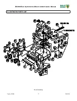
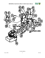
Page 17: ...Part No 501606 17 F041513B BC2600 Euro Hydro Series Brush Cutter Owner s Manual ILLUSTRATED PARTS LIST Deck Assembly...

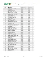
Page 18: ...X 06 THK 850238 1 850238 1 32 WASHER LOCK 3 8 S T MED 8177012 1 8177012 1 33 WASHER 1 5 OD X 453 ID X 25 THK 440153 1 440153 1 34 TUBE PIVOT IDLER VQ 830526 1 830526 1 35 PULLEY IDLER 4 00 OD X 3 8 BO...

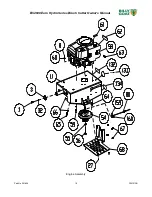
Page 19: ...Part No 501606 19 F041513B BC2600 Euro Hydro Series Brush Cutter Owner s Manual Engine Assembly...

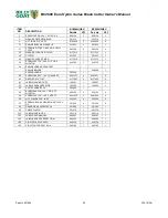
Page 20: ...DA ELEC START ENGINE BRIGGS 520046 1 ENGINE HONDA 500334 1 59 SCREWCAP 5 16 18 X 1 3 4 HCS ZP 8041031 2 8041031 2 60 WASHER 5 16 FLAT 8171003 4 8171003 4 61 LABEL WARNING FUEL 100261 1 100261 1 62 LAB...

Page 21: ...Part No 501606 21 F041513B BC2600 Euro Hydro Series Brush Cutter Owner s Manual Handle Assembly...

Page 22: ...1028 2 8041028 2 79 WASHER LOCK 5 16 S T MED 8177011 2 8177011 2 80 CABLE CLUTCH 501279 1 501279 1 81 LEVER CONTROL BLADE 500312 1 500312 1 82 CONTROL THROTTLE 440013 1 440013 1 83 NUT LOCK LT 10 24 H...

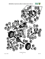
Page 23: ...Part No 501606 23 F041513B BC2600 Euro Hydro Series Brush Cutter Owner s Manual Transaxle Drawing...

Page 24: ...EWCAP 1 4 20 X 1 3 4 SKT BUT HD 840199 2 840199 2 107 CABLE SPEED CONTROL RT 501276 1 501276 1 108 WASHER 1 4 SAE 8172007 2 8172007 2 109 NUT LOCK 5 8 11 LT WT TH ZP 8161046 1 8161046 1 110 BOLT SHOUL...

Reviews: