6
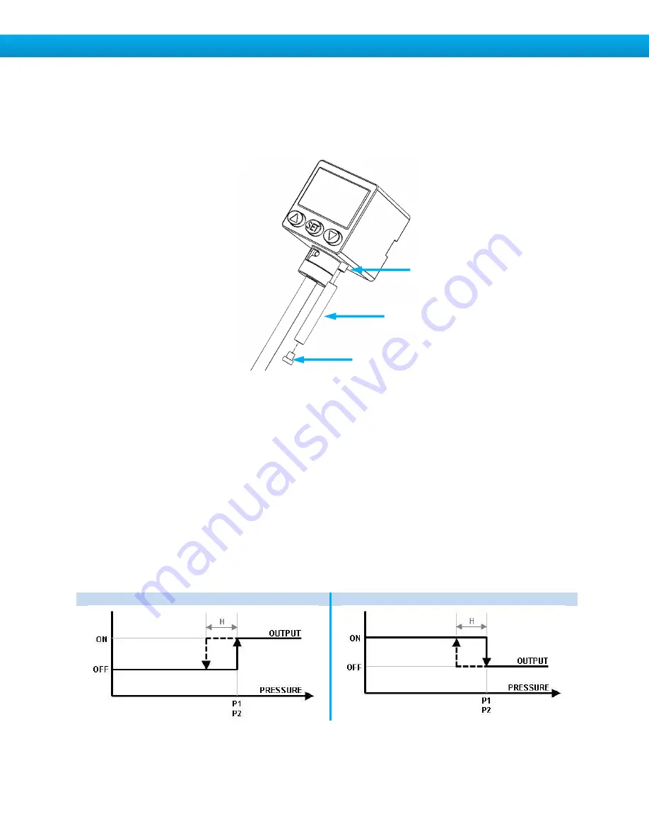
Sensor Breather Port
DPS series switches include a vent port located on the bottom of the switch housing. The vent
port allows atmospheric pressure to the sensor for accurate measurement. To maintain IP65
enclosure protection, install the supplied tube and sintered breather on the vent port. Or, use a
2.5mm I.D. tube to pipe the breather port to a clean, dry location. Do not attempt to pressurize
the breather port, sensor damage will result.
Digital Output Modes
Each digital output has three field-programmable output modes and can be configured as
normally-open or normally-closed. In normally-open mode, the switch contact is made when the
output is active. In normally-closed mode, the switch contact is broken when the output is active.
For information on setting the output contact mode (NC or NO) see the “Initial Settings” section.
Point Set Mode
Point set mode enables the digital output when pressure increases above the setpoint (P1 or
P2) and disables the output when pressure falls below the setpoint minus system hysteresis.
See “Setting Digital Outputs” for information on setting P1 and P2. System hysteresis can be
adjusted between 1 and 8 decimal places. See
“Advanced Settings” for further information on
adjusting system hysteresis.
Normally-Open Contact Mode
Normally-Closed Contact Mode
H = System hysteresis
Breather Port
Supplied Tube
Supplied Breather


