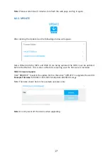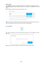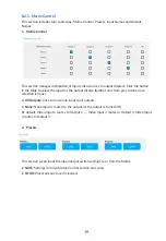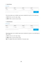
9
4.
DEVICE LAYOUT
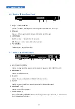
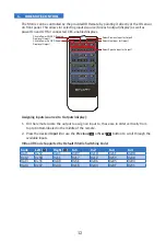
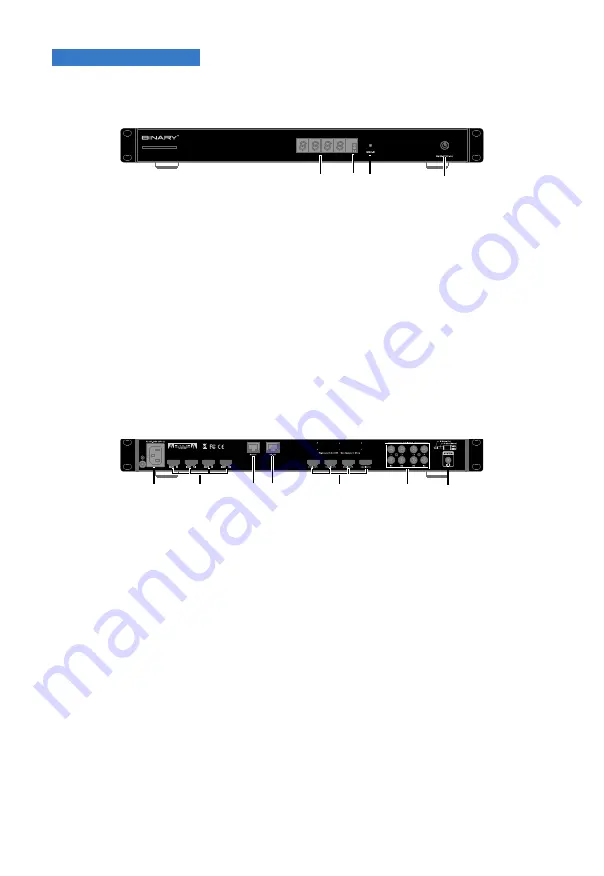
4.1. B-660-MTRX-4x4 Front Panel
1
3
2
4
1. Output Channel Indicator
Indicates input for output port 1-4 showing the input related to the output.
2. IR Sensor
Receives IR from handheld IR Remote, IR Emitter, or IR Flasher.
3. STATUS LED
On
:
The device is connected to the network.
Off
: The device is not connected to the network.
4. Power Switch
Press to power on/off the matrix.
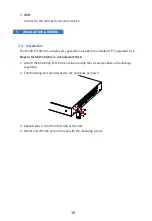
4.2. B-660-MTRX-4x4 Rear Panel
1
3
4
2
5
6
7
1. AC 100-240V 50/60Hz
Connect to the provided power cord. Accepts AC power of 100-240V 50/60Hz.
2. HDMI IN (1-4)
Connect to HDMI Sources.
3. Network
Connect to a control system for Web UI or Telnet control.
4. RS-232
Connect to a control PC or control system for RS-232 serial control.
5. HDMI OUT (1-4)
Connect to an HDMI displays.
6. AUDIO OUT 1-4
For de-embedding 2ch PCM audio to L/R analog audio output. Connect to audio devices
via RCA stereo audio cables.


