KBF + KMF (E6) 07/2017
page 79/155
12.3.1 Temperature safety device class 3.1
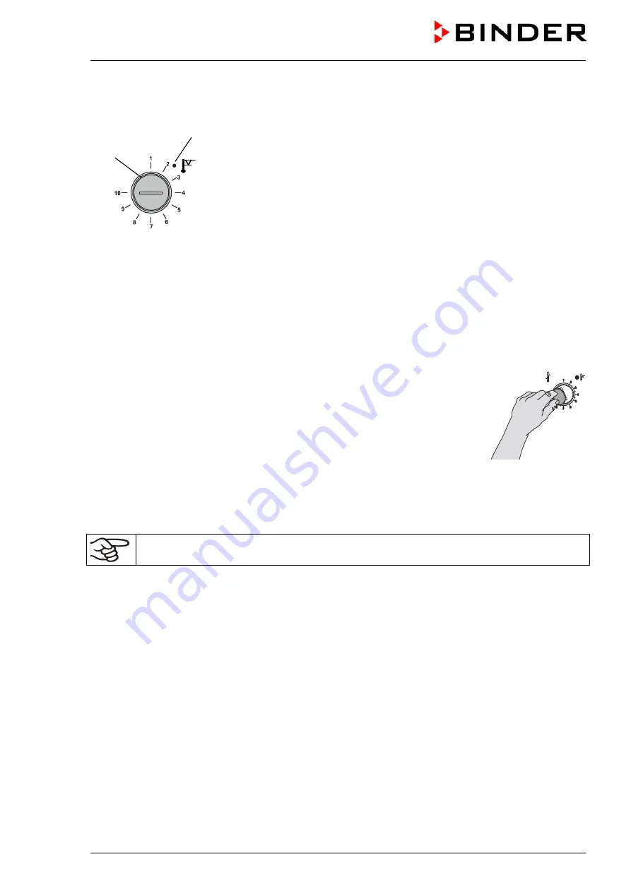
If you turn the control knob (8) to its end-stop (position 10), the safety device
class 3.1 protects the appliance. If you set the temperature a little above the
set-point, it protects the charging material.
If the safety device class 3.1 has taken over control, identifiable by the red
alarm lamp (8a) lighting up, the message “Temp. safety device” on the con-
troller will be displayed and the buzzer will sound, then proceed as follows:
•
Reset the buzzer by pressing the “RESET” key on the controller
•
Disconnect the chamber from the power supply
•
Have an expert examine and rectify the cause of the fault.
•
Start up the chamber again
Setting:
To check the response temperature of the safety device class 3.1, turn on the chamber and set the de-
sired set point at the temperature controller.
The sections of the scale from 1 to 10 correspond to the temperature range from 0 °C /
32 °F
to 120 °C /
248 °F
and serve as a setting aid.
•
Turn the control knob (8) of the safety device using a coin to its end-stop (posi-
tion 10) (chamber protection).
•
When the set point is reached, turn back the control knob (8) until its trip point
(turn it counter-clockwise).
•
The trip point is identifiable by the red alarm lamp (8a), the message “Temp.
safety device” on the controller display, and the buzzer sounds. Reset the
buzzer with the “RESET” key on the controller.
•
The optimum setting for the safety device is obtained by turning the control
knob clockwise by approximately two scale divisions, which shuts off the red
alarm lamp (8a).
Figure 17: Setting
safety device class
3.1
Check the setting regularly and adjust it following changes of the set-point or charge.
Function check:
Check the temperature safety device class 3.1 at appropriate intervals for its functionality. It is recom-
mended that the authorized operating personnel should perform such a check, e.g., before starting a
longer work procedure.
(8a)
(8)
Summary of Contents for KBF 115
Page 137: ...KBF KMF E6 07 2017 page 137 155 23 8 Dimensions size 115 ...
Page 138: ...KBF KMF E6 07 2017 page 138 155 23 9 Dimensions size 240 ...
Page 139: ...KBF KMF E6 07 2017 page 139 155 23 10 Dimensions size 720 ...
Page 140: ...KBF KMF E6 07 2017 page 140 155 23 11 Dimensions size 1020 ...
Page 142: ...KBF KMF E6 07 2017 page 142 155 ...
Page 143: ...KBF KMF E6 07 2017 page 143 155 ...
Page 144: ...KBF KMF E6 07 2017 page 144 155 24 2 EU Declaration of Conformity for KMF ...
Page 145: ...KBF KMF E6 07 2017 page 145 155 ...
Page 146: ...KBF KMF E6 07 2017 page 146 155 ...
Page 148: ...KBF KMF E6 07 2017 page 148 155 ...
Page 149: ...KBF KMF E6 07 2017 page 149 155 25 Product registration ...


