


8
VRF180913 Rev. A
www.bindicator.com
8
Note: The VRF II Series incorporates pluggable terminal blocks for ease of connection. If the terminal block is
unplugged while making connections, ensure it is seated properly when reinstalled.
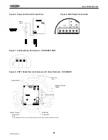
5. Attach power leads to terminal block as shown in Figure 5.
6. Check that all wires are held tightly in place by lightly pulling each conductor.
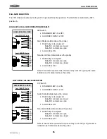
Main Relay Connections
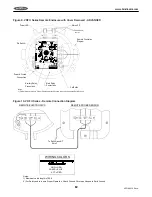
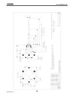
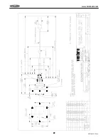
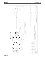
7. Refer to Figure 3 or 4 and 6 when connecting to the main relay.
8. Pull approximately 4.5” (11.43 cm) of cable through conduit and strip
1
/
4
” (6 to 7 mm).
9. Attach leads to terminal block as shown in Figure 5.
10. Check that all wires are held tightly in place by lightly pulling each conductor.
For STANDARD models skip to Step 15; for ADVANCED models continue to Step 11.
Auxiliary Relay Connections
11. Refer to Figure 3 or 4 and 7 when connecting to the auxiliary relay.
12. Pull approximately 5.5” (13.97 cn) of cable through conduit and strip
1
/
4
” (6 to 7 mm).
13. Attach leads to terminal block as shown in Figure 5.
14. Check that all wires are held tightly in place by lightly pulling each conductor.
15. Reinstall the gasket, if necessary.
16. Replace cover and tighten screws to 60 in-lb (6.8 n-m) of torque.
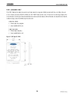
VRF II SERIES REMOTE MODEL ONLY
Input Power Connections
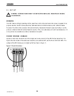
1. Refer to Figures 3 or 4 and 5 when connecting input power to the unit.
2. Loosen set screw that locks cover in place.
3. Unscrew the housing cover and remove.
Note: Two threaded female conduit openings are provided in the remote housing to separate input and output
wiring from the remote probe wiring.
4. Pull approximately 6” (15 cm) of cable through conduit closest to grounding bracket and strip as follows:
a. Ground –
3
/
8
” (9 to 10 mm)
b. Power Leads –
1
/
4
” (6 to 7 mm)
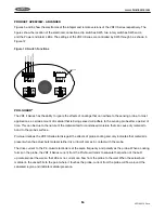
5. Attach incoming ground lead to grounding bracket as shown in Figure 5.
Note: The VRF II Series incorporates pluggable terminal blocks for ease of connection. If the terminal block is
unplugged while making connections, ensure it is seated properly when reinstalled.
6. Attach power leads to terminal block as shown in Figure 3 or 4.
7. Check that all wires are held tightly in place by lightly pulling each conductor.
Summary of Contents for VRF II Series
Page 1: ...IOMVRF180713 Rev A VRF II Series Installation Operation Manual IOMVRF180913 Rev A ...
Page 2: ......
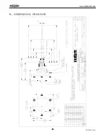
Page 24: ...20 VRF180913 Rev A www bindicator com 20 IX DIMENSIONAL DRAWINGS venture ...
Page 25: ...21 www bindicator com VRF180913 Rev A 21 ...
Page 26: ...22 VRF180913 Rev A www bindicator com 22 venture ...
Page 27: ...23 www bindicator com VRF180913 Rev A 23 ...
Page 28: ...24 VRF180913 Rev A www bindicator com 24 Optional Lights venture ...
Page 29: ...25 www bindicator com VRF180913 Rev A 25 Optional Lights ...
Page 30: ...26 VRF180913 Rev A www bindicator com 26 Notes ...
Page 31: ...27 www bindicator com VRF180913 Rev A 27 Notes ...


