


12
VRF180913 Rev. A
www.bindicator.com
12
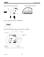
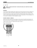
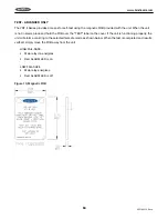
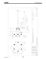
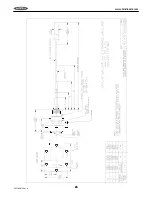
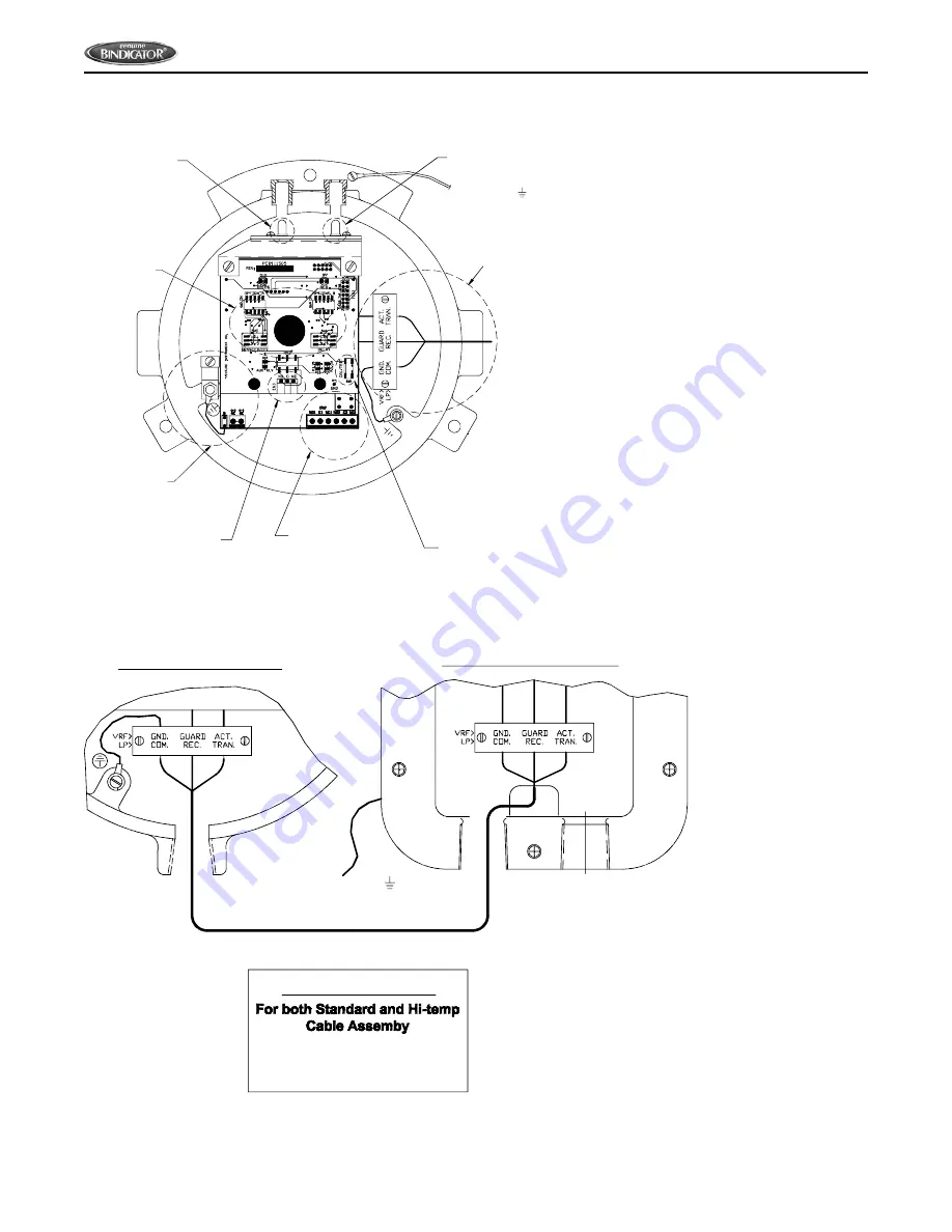
Figure 9. VRF II Series Remote Enclosure with Cover Removed - ADVANCED
Auxillary Relay
Connections
Power & Ground
Connections
Dip Switch
Power LED
Remote Connection
Diagram
Alarm LED
Main Relay
Connections
Cal Button
To Earth Ground
Note 1
Notes:
1) For Safety and to insure Proper Operation, Attach Ground Wire to an Adequate Earth Ground.
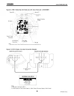
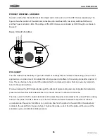
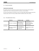
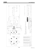
Figure 10. VRF II Series - Remote Connection Diagram
GND.=
GUARD =
ACT.=
GRN
BLUE
RED
WIRING COLORS
Remote Connection Diagram
REMOTE ELECTRONICS
REMOTE PROBE SENSOR
To Earth Ground
Note 2
Notes:
1) Maximum cable length is 100ft.
2) For Safety and to insure Proper Operation, Attach Ground Wire to an Adequate Earth Ground.
Summary of Contents for VRF II Series
Page 1: ...IOMVRF180713 Rev A VRF II Series Installation Operation Manual IOMVRF180913 Rev A ...
Page 2: ......
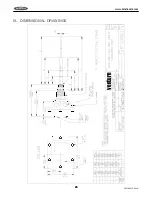
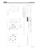
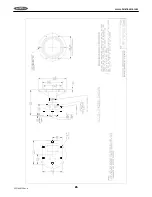
Page 24: ...20 VRF180913 Rev A www bindicator com 20 IX DIMENSIONAL DRAWINGS venture ...
Page 25: ...21 www bindicator com VRF180913 Rev A 21 ...
Page 26: ...22 VRF180913 Rev A www bindicator com 22 venture ...
Page 27: ...23 www bindicator com VRF180913 Rev A 23 ...
Page 28: ...24 VRF180913 Rev A www bindicator com 24 Optional Lights venture ...
Page 29: ...25 www bindicator com VRF180913 Rev A 25 Optional Lights ...
Page 30: ...26 VRF180913 Rev A www bindicator com 26 Notes ...
Page 31: ...27 www bindicator com VRF180913 Rev A 27 Notes ...


