background image

11

Your new Binks Century Gun will give you excellent performance
as long as it is handled properly. Read over these sections before
operating the gun.

CATALYZATION

The catalyst orifice should be sized to minimize catalyst pres-
sure. Over-catalyzation can show up as a split pattern, misting
of the resin, streaking of the catalyst in the resin, or detection
of catalyst fumes. A wide range of catalyst injectors is avail-
able to accommodate your specific needs. Refer to the 

Catalyst

Injector Selection Chart

for the various orifice sizes.

Catalyst fumes should be minimal. The Binks Century guns
utilize external advanced catalyzation technology, “EXACT”
which mixes all of the catalyst exiting the catalyst injector into
the resin stream.

FLUID/AIR PRESSURE OF THE RESIN/GEL-COAT

To reduce overspray and obtain maximum efficiency of the
Century gun, the fluid and air pressure should be reduced to
their lowest possible pressures that produce acceptable
atomization and finish.

Typically, for unfilled resins and unpigmented gel-coats, the fluid
pressure needed for proper atomization is approximately 200-700
psi. For filled resins and pigmented gel-coats, the fluid pressure
will be significantly higher, approximately 400-1500 psi.

Depending on your system, the fluid pressures you use will vary
higher or lower than these numbers, but they serve as a good
starting point.

Typically, the pressure setting at nozzle for the atomizing air
will be from 3 to 10 psi, although pressures up to 30 psi are
acceptable. The atomizing air is necessary for proper catalyza-
tion and therefore should not be reduced below 5 psi. Also,
depending upon the catalyst, it may be necessary to
increase/decrease the atomizing air in order to induce proper
catalyzation after determining the necessary air pressure for a
good spray pattern.

TIMING OF THE AIR, CATALYST AND 
RESIN VALVES

The timing of the air, catalyst and resin valves is an important
factor in the operation of the Century gun.

The gun will appear to leak if the lag between engaging the
atomizing air and the fluid needles is unnecessarily long.
While releasing the trigger, the resin and catalyst shut off first
and the atomizing air has not shut off yet. The atomizing air
will then siphon out any remaining material in the spray tip
and/or catalyst injector. This is why it is necessary to adjust the
nuts on the resin and catalyst needles so that there exists only a
very short interval between the actuation of the atomizing air
and the fluid needles.

(continued)

OPERATING INSTRUCTIONS
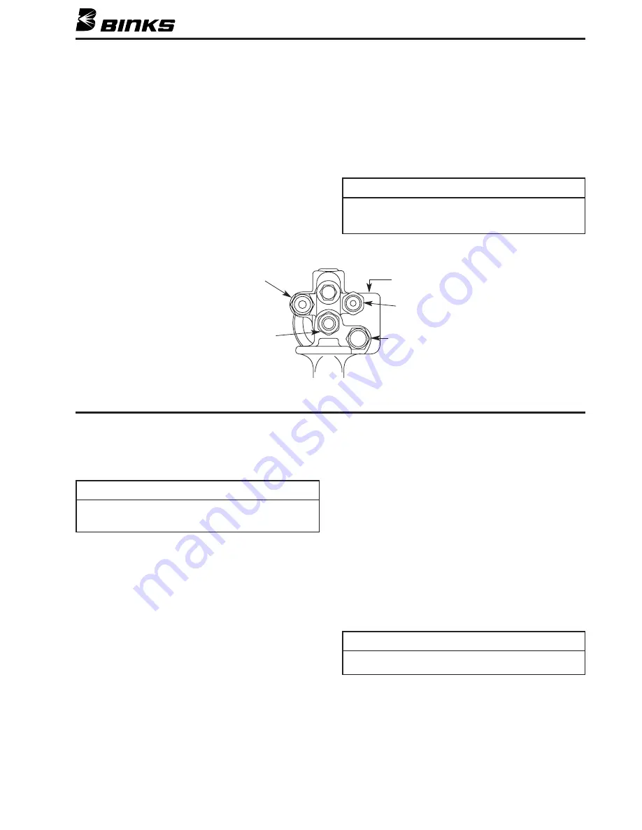
REAR VIEW OF GUN

NOTE: All inlets are 1/4" male.

(For 102-2400, 102-2455 and 102-2500)

Resin

Inlet

Air Assist

Inlet

Chopper Air

Outlet

Catalyst

Inlet

Chopper Air

Inlet

1. Connect air hose to air assist inlet (53) and tighten securely.

Set regulator to provide sufficient air at nozzle (3-10#).

2. Connect high pressure airless fluid hose from the resin

pump to the resin inlet assembly (48) and tighten securely.
Set pumping source to deliver resin from 500-1500 psi.

3. Connect the catalyst hose to the catalyst inlet/filter assem-

bly (42) and tighten securely.

4. If using chopper (102-2400 gun), connect the chopper air

hose to the chopper air inlet (52) and tighten securely.

5. Loosen the two nuts on the catalyst needle (24 & 25) and

move them forward so that the trigger actuates them simul-
taneous with engagement of the resin needle. Once fin-
ished, reposition them again so that they are engaged just
as the resin needle nut is engaged when triggering the gun.

6. Assemble the spray tip assembly and the air/catalyst cap

and tighten the air/catalyst cap retainer ring (1) securely.

7. Set fluid pressure to achieve low pressure airless pattern

with “fingers”.

8. Adjust atomizing air until the “fingers” have been removed

from the spray pattern and proper atomization has been
achieved. If atomizing air seems excessive (overspray)
increase fluid pressure and reduce air. (Check pattern).
(Excessive atomizing air can impair catalyzation.)

SET-UP INSTRUCTIONS

NOTE

Century guns are considered HVLP (high volume, low
pressure). Air required for atomization is in the 3-10#
range at nozzle.

NOTE

Whenever the gun is not in operation set the trigger lock by
rotating the trigger (62) as far forward as it will go and then
rotating the locking block (68) in its upward orientation.

NOTE

The sequence of operation is: atomizing air, catalyst and
resin simultaneously.

Summary of Contents for 102-2400

Page 1: ...WAYS handle carefully all hose connections joints and seating surfaces on the spray gun to prevent dam age b NEVER kink or bend the fluid hose into less than a four inch radius c FREQUENTLY check the hose for kinks or abrasions These may develop into a rupture d NEVER use standard hardware to modify the airless system ALWAYS use Binks high pressure fittings only 6 The airless pump must be grounded...

Page 2: ...HAZARD Improper equipment grounding poor ventilation open flame or sparks can cause hazardous conditions and result in fire or explosion and serious injury PINCH POINT HAZARD Moving parts can crush and cut Pinch points are basically any areas where there are moving parts KNOW WHERE AND HOW TO SHUT OFF THE EQUIPMENT IN CASE OF AN EMERGENCY PRESSURE RELIEF PROCEDURE Always follow the pressure relief...

Page 3: ...IER If you are now using a Halogenated Hydrocarbon Solvent in a pressurized fluid system with aluminum components or galvanized wetted parts the following steps should be taken immediately 1 Remove all pressure drain and disconnect the entire system 2 Inspect and replace all corroded parts 3 Contact your solvent supplier for a NON HALOGENATED SOLVENT to flush and clean the system of all residues H...

Page 4: ... 20 21 18 11 13 12 14 15 16 17 35 34 36 37 33 38 39 40 55 61 48 43 41 85 66 64 65 64 24 25 89 68 62 63 54 60 59 58 57 56 28 17 29 88 84 49 50 87 86 31 32 3 4 5 51 52 53 44 45 46 47 42 VIEW A VIEW A Note Items 24 and 68 not available separately Resin Seat 10 not part of head Assembly 9 ...

Page 5: ... 1 51 102 2409 HEAD RETAINER 1 52 102 2467 CHOPPER AIR INLET 1 53 102 2403 AIR ASSIST INLET 1 54 102 2470 CHOPPER TRIGGER ASSEMBLY 1 55 102 2471 CHOPPER TRIGGER 1 56 102 2472 ON OFF SELECTOR 1 57 102 2474 LOW FRICTION WASHER 1 58 102 2475 WAVE SPRING 1 59 102 2473 RETAINER SCREW 1 60 54 1020 TRIGGER STUD 1 61 82 126 TRIGGER SCREW 1 62 102 2489 TRIGGER 1 63 102 2404 GUARD STUD 1 64 102 2405 GUARD A...

Page 6: ...3 38 39 40 61 48 43 78 83 66 64 65 64 24 25 86 68 62 63 80 3 4 5 44 45 46 47 42 VIEW A Note Items 24 and 68 not available separately Note A Carbide Seat 102 2446 is standard on Model 102 2500 for Item 10 Resin Seat 10 not part of head Assembly 9 102 2500 GEL COAT CENTURY GUN 75 49 50 75 53 51 VIEW A ...

Page 7: ...T 1 47 102 2441 MATERIAL INLET Catalyst 1 48 102 2435 RESIN INLET ASSEMBLY 1 49 20 3111 PIPE PLUG 1 50 102 2408 GASKET 1 2 I D x 615 O D 1 51 102 2409 HEAD RETAINER 1 53 102 2403 AIR ASSIST INLET 1 61 82 126 TRIGGER SCREW 1 62 102 2489 TRIGGER 1 63 102 2404 GUARD STUD 1 64 102 2405 GUARD ASSEMBLY 1 65 20 6295 SCREW 5 16 24 x 5 8 B H 1 66 54 714 AIR PLUG 1 67 102 2494 NIGHT CAP ASSEMBLY 1 68 LOCKIN...

Page 8: ... 38 39 40 61 48 43 78 83 66 64 65 64 24 25 86 68 62 63 80 3 4 5 44 45 46 47 42 VIEW A Note Items 24 and 68 not available separately Note A Carbide Seat 102 2446 is standard on Model 102 2545 for Item 10 Resin Seat 10 not part of head Assembly 9 102 2545 VINYL ESTER CENTURY GUN 75 49 50 75 53 51 VIEW A ...

Page 9: ... 1 47 102 2441 MATERIAL INLET Catalyst 1 48 102 2478 RESIN INLET ASSEMBLY 3 8 1 49 20 3111 PIPE PLUG 1 50 102 2408 GASKET 1 2 I D x 615 O D 1 51 102 2409 HEAD RETAINER 1 53 102 2403 AIR ASSIST INLET 1 61 82 126 TRIGGER SCREW 1 62 102 2489 TRIGGER 1 63 102 2404 GUARD STUD 1 64 102 2405 GUARD ASSEMBLY 1 65 20 6295 SCREW 5 16 24 x 5 8 B H 1 66 54 714 AIR PLUG 1 67 102 2494 NIGHT CAP ASSEMBLY 1 68 LOC...

Page 10: ...O 108 93605 0 036 5 3605 108 93607 0 036 7 3607 108 93609 0 036 9 3609 108 94107 0 041 7 4107 108 94109 0 041 9 4109 108 94405 0 044 5 4405 108 94407 0 044 7 4407 108 94409 0 044 9 4409 108 95107 0 051 7 5107 108 95109 0 051 9 5109 108 95707 0 057 7 5707 108 96307 0 063 7 6307 Refer to Part Sheet 77 2475 for Chopper Assembly NOTE Additional tip seals available in 106 1177 Tip Seal Kit ITEM PART NO...

Page 11: ...ssarily long While releasing the trigger the resin and catalyst shut off first and the atomizing air has not shut off yet The atomizing air will then siphon out any remaining material in the spray tip and or catalyst injector This is why it is necessary to adjust the nuts on the resin and catalyst needles so that there exists only a very short interval between the actuation of the atomizing air an...

Page 12: ...tio is set record air pressure to both Tank and air motor and ball level on flow meter If shop temperature does not vary flow will remain constant CHOPPER TRIGGER OPERATION 102 2400 GUN ONLY The Century gun is equipped with a special chopper trigger 54 This device allows simple on off capabilities plus the ability to run load the chopper without triggering the gun at all To set the chopper trigger...

Page 13: ...e yourself and or nearby personnel REPLACING THE CATALYST NEEDLE PACKING 1 Using two standard screwdrivers remove the trigger stud 60 the trigger screw 61 the trigger 62 and the chopper trigger assembly 54 2 Unscrew the catalyst packing nut 23 with a 3 8 wrench and pull the catalyst needle assembly 19 straight back until it comes out of the gun head Be sure to pull the needle out without bending i...

Page 14: ...nt of the gun head with the three large grooves against a clean flat surface A one inch diameter with a minimum depth of 3 4 would allow the gun head to rest in this manner 11 Put the new resin seat into the center hole of the gun head that goes thru the alignment cone in the back of the gun head The small end of the resin seat must go in first The seat should drop into the gun head 12 The seat no...

Page 15: ... NEEDLE ASSEMBLY 1 Repeat steps 1 and 2 from the section Replacing the Catalyst Needle Packing above 2 Replace worn needle assembly with new needle assembly 3 Reassemble in reverse order REPAIRING THE AIR ASSIST VALVE ASSEMBLY 1 Repeat steps 1 and 2 from section Replacing the Resin Needle Packing 2 Using a 9 16 wrench remove the air assist valve assembly 33 seal 38 and spring 39 3 Remove the nut 3...

Page 16: ...ice Office 195 Internationale Blvd Glendale Heights IL 60139 Toll Free Telephone 1 888 992 4657 U S A and Canada only Toll Free Fax 1 888 246 5732 Binks Worldwide Sales and Service Listing www binks com WARRANTY This product is covered by Binks 1 Year Limited Warranty 77 2520R 8 Revisions PP1 8 9 Added content for 102 2545 Vinyl Ester Century Gun P4 Edited footnote P5 Edited Parts List P6 Edited f...

Reviews: