


14
6. Put the new catalyst seat into the hole of the gun head that
the catalyst needle assembly came out of. The small end
of the catalyst seat must go in first. The seat should drop
down into the gun head.
7. The seat now needs to be pressed into place such that a
tight fit is created between the resin seat and the walls of
the gun head that retain it. Use a 1/4" diameter dowel to
press the seat tight. Be careful not to scratch the walls of
the gun head. A drill press or arbor press is best for this
operation.
8. Reassemble in reverse order.
REPLACING THE RESIN SEAT
(Original Style Gun Head)
1. Remove air/catalyst cap retainer ring (1), air/catalyst
cap (2), the spray tip assembly (5), and the two
o-rings (7 & 8) from the gun head.
2. Remove the button head screw (65) that retains the guard
assembly (64) by using a 3/16" allen wrench; remove the
guard assembly.
3. Using two standard screwdrivers, remove the trigger stud
(60), the trigger screw (61), the trigger (62), and the chop-
per trigger assembly (54).
4. Using a 3/8" wrench or socket, remove the head retainer
(51).
5. Remove the catalyst inlet/filter assembly (42) using a
7/16" wrench and the resin inlet assembly (48) with a
9/16" wrench.
6. Remove the gun head from the handle (41).
7. Unscrew the resin packing nut (15) with a 3/8" wrench
and pull the resin needle assembly (11) straight back until
it comes out of the gun head. Be sure to pull the needle
out without bending it up and down or side to side, as this
will cause the needle to bend, thus ruining the needle.
8. Place gun head on a flat clean surface with the back of the
gun head against the surface. This will require a hole or
recess in the surface such that the alignment cone on the
back of the gun head does not rest against anything. A
hole with at least a one inch diameter and a minimum
depth of 3/4" is required.
9. Align 13/64" dowel pin (70) (available in Repair Kit
106-1171) with the center hole of the gun head. Move the
dowel pin straight down into the center hole of the gun
head until it seats against the resin seat (10), about a 1/2"
from the top surface of the gun head. Press the seat out.
This is most easily done on a drill press or arbor press.
10. Now place the front of the gun head with the three large
grooves against a clean flat surface. A one inch diameter
with a minimum depth of 3/4" would allow the gun head
to rest in this manner.
11. Put the new resin seat into the center hole of the gun head
that goes thru the alignment cone in the back of the gun
head. The small end of the resin seat must go in first.
The seat should drop into the gun head.
12. The seat now needs to be pressed into place such that a
tight fit is created between the resin seat and the walls of
the gun head that retain it. Use 3/8" dowel pin (71) to
press the seat tight. Be careful not to scratch the walls of
the gun head. A drill press or arbor press is best for this
operation.
13. Reassemble in reverse order.
REPLACING RESIN SEAT
(New Forged Style Gun Head)
1. Remove air/catalyst cap retainer ring (1), air/catalyst cap
(2), the spray tip assembly (5), and the two o-rings
(7 & 8) from the gun head.
2. Pull the trigger (62) to unseat needle from the seat (10)
and remove head insert (72) with a 13/16" wrench.
Remove seal (73) and replace with new seal.
3. Place head insert on a flat clean surface with the back of
the hex of the head insert against the surface. This will
require a hole or recess in the surface such that the head
Insert does not rest against anything. A 9/16" diameter
hole with a minimum depth of one inch would accommo-
date this. Align 13/64" dowel pin (70) (available in Repair
Kit 106-1171) with the center of the hole of the head
insert. Move the dowel pin straight down until it seats
against the resin seat (10). This will be about 1/2" from
the top surface to the head insert. Press the seat out. This
is most easily done on a drill press or arbor press.
4. Now place the front of the head insert with grooves
against a flat clean surface.
5. Put the new resin seat into the tapered hole of the head
insert. The small end of the resin seat must go in first. The
seat now needs to be pressed in place such that a tight fit
is created between the resin seat and the walls of the head
insert that retain it. Use 3/8" diameter dowel pin (71)
(available in Repair Kit 106-1171) to press the seat
tight. A drill press or arbor press is best for this operation.
6. Reassemble in reverse order.
REPLACEMENT OF WORN PARTS (
continued
)
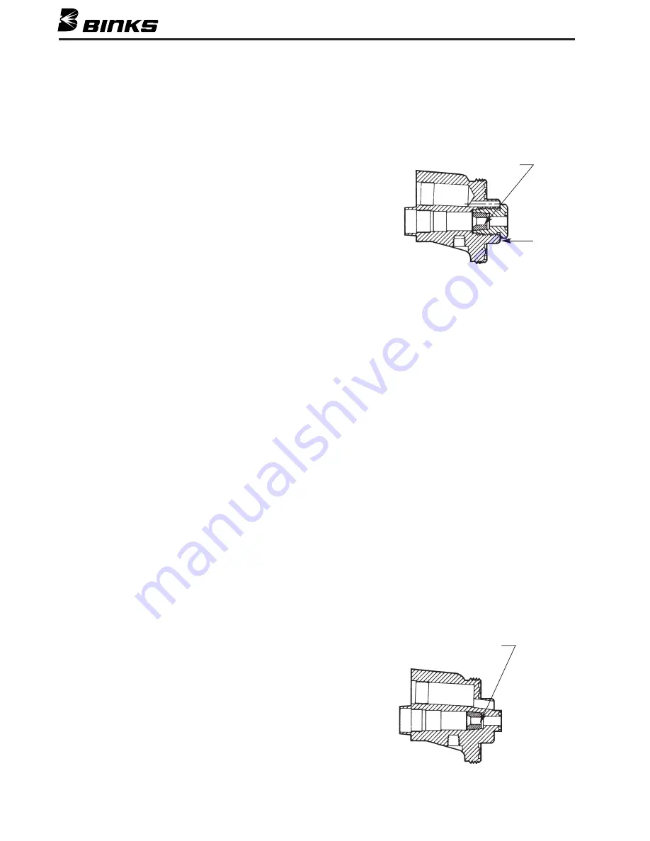
SEAT (10)
A
NOTE:
Head insert (72)
must be tightened
down flush to
surface “A”.
SEAT (10)
ORIGINAL CAST HEAD DESIGN
NEW-STYLE FORGED HEAD DESIGN


