


©BINKS 1999 –SB-E- A1-2
3
CONNECTING GUN TO AIR HOSE
Gun should be connected by a suitable length of
5
/
16
” (7.94 mm) bore air hose fitted with a connector with a 1/4” B.S.P union nut at
gun end. It is recommended that the air supply be filtered to 50 microns maximum, however alternative air preparation may be
required for special applications.
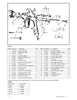
CONTROLLING THE MATERIAL FLOW
The rate of flow is adjusted by the Material Valve Control Screw (19) which acts as an adjustable stop limiting the travel of the
Material Needle Valve. Turning it clockwise will reduce the rate of flow and anti clockwise will increase flow. When used with a
gravity cup an increase in air pressure will increase the rate of flow.
ADJUSTMENT OF MATERIAL NEEDLE VALVE
The needle valve assembly is adjustable for length by means of the needle locking screw and needle end assembly. These should
be adjusted so that when the trigger is in contact with the air valve stem there is about 1/32” (.79 mm) clearance between the trigger
and the needle assembly . In no circumstances must the needle valve open before the air valve.
CONTROLLING THE FAN SPRAY
The fan spray is controlled by means of the Side Port Control (26) Turning this control clockwise until it is closed will give a round
spray; turning it anti-clockwise will widen the spray into a fan shape. The fan spray can be turned anywhere through 360 by rotating
the Air Nozzle (33) relative to the gun. To effect this - slacken retainer ring, position Nozzle (33) then tighten retainer ring.
CONNECTING GUN TO MATERIAL HOSE
Gun should be connected by a suitable length of
3
/
8
” bore (9.5 mm) material hose fitted with a connector with a
3
/
8
“ B.S.P union nut
at the gun end
1
/
4
” (6.35 mm) bore hose is recommended for use with low viscosity materials. Fluid hoses of different materials are
available for special fluids.
CONNECTING GUN TO SYPHON CUPS
The union nut of the cup should be attached to the material connection of the gun and firmly tightened. It is important that there is no
leakage at this point. The syphon pipe should be positioned at the front of the gun. i.e under the nozzles, and the vent hole in the
cup lid positioned under the trigger.
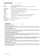
OPERATION
Body:
Aluminium alloy polished and anodised.
Air Nozzle:
Hard brass stamping, bright electroless nickel plated with taper location on material nozzle to
ensure concentricity.
Material Nozzle:
Hardened steel, located in body and in air nozzle by tapers.
Needle Valve:
Stainless Steel or nylon with adjustable sleeve to compensate for wear “V” suffix has Tungsten Carbide tip.
Trigger:
Aluminium Stamping for strength and reduced weight.
Air Valve:
Nylon valve with stainless steel stem and adjustable seal.
Springs:
All springs are stainless steel.
Connections:
Air inlet connection is 1/4” BSP and fluid connection is 3/8” BSP (NPS available)(All 60
o
Cone).
Finish:
Gun body red anodised. Trigger highly polished, all brass parts are nickel plated.
Weight:
0.62 kg (1Ib. 6 oz).
Dimensions:
Less Cup (17. 5 X 3.65 X19 cm) (6
7
/
8
long X 1
7
/
16
wide x 7
1
/
2
” high).
Max Working Pressure:
Air & Fluid 10 bar (145 psi)
Max Fluid Temp:
50
0
C (122
0
F)
SPECIFICATIONS


