background image

EN

77-1153-R25.1  (8/2014)

8 / 12


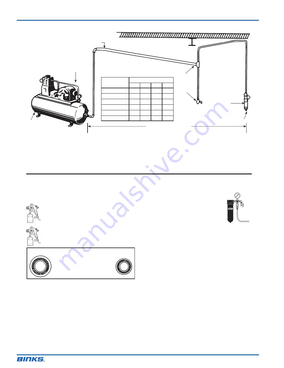
Length of Pipe (feet)


Air Flow

  CFM 

50  100 150 200


10 

1/2” 3/4” 3/4”


20 

3/4” 3/4” 3/4” 3/4”


30 

3/4” 3/4”  1”  1”

  40 

1” 1” 1” 1”

  50 

1” 1” 1” 1”


70 

1” 

1”  1-1/4” 1-1/4”

AIR SUPPLY

The Clean Air™ filter should not be mounted on or 

near the air compressor.

The temperature of air is greatly increased during compression. As the 
air cools down to room temperature, in the air line, on its way to the 
spray gun, the moisture contained in it condenses. Thus, for maximum 
effectiveness, the oil and water extractor should be mounted at some 
point in the air supply system where the temperature of the 
compressed air in the line is likely to be lowest.

Air lines must be properly drained.

Pitch all air lines away from the compressor so that condensed moisture 
can be drained off. Each low point in an air line acts as a water trap. Such 
points should be fitted with an easily accessible drain. See diagram above.

PIPE SIZE, I.D. (inches)

Install  

drain  

at each  

low point

Compressor unit

Drain

Pitch pipe away from air receiver

Oil and 

water 

extractor

Drain

25 FEET OR MORE

Oil and Water Extractor should be at least 25 ft. from the compressor. Further if possible.

Air pressure at the gun is important.

Atomizing pressure must be set to allow for the drop in air pressure 
between the regulator and the spray gun.

A DeVilbiss Clean Air™ filter is important.

A Clean Air™ filter serves a double purpose. It 
eliminates blistering and spotting by keeping air 
free from oil and water... and its precision air 
regulator makes possible perfect air pressure 
control at the gun.
The best spray gun in the world will not operate 
efficiently without a good compressor and a 
Clean Air™ filter. Model HFRL-508 is recommended.
If you are attempting to get a fine  finish without the use of a Clean Air™ 
filter you will not succeed.

Cross section view showing 

comparison of inside hose 

diameters (actual size).  

60 lbs. regulated pressure

5/16”

1/4”

Only 44 PSI
25 feet of 1/4” I.D. hose causes a drop of 16 PSI 

between the air supply and the gun.

Only 55 PSI
25 feet of 5/16” I.D. hose has a drop of only 5 PSI. 

For this reason we recommend the use of 5/16” hose.

AIR PRESSURE

Summary of Contents for 7

Page 1: ...n Air filter Figure 5 Air Fluid Fluid Regulator Fluid Figure 4 Air Supply Air Supply Pressure Tank Clean Air filter Air Inlet Figure 3 Air Pressure Tank Fluid PRESSURE FEED TANK HOOKUP For portable painting operations double regulator Air pressure for atomization and fluid supply is regulated by two individual air regulators on tank see figure 4 PRESSURE FEED CIRCULATING HOOKUP For heavy productio...

Page 2: ...RELIEF PROCEDURE Always follow the pressure relief procedure in the equipment instruction manual NOISE HAZARD You may be injured by loud noise Hearing protection may be required when using this equipment STATIC CHARGE Fluid may develop a static charge that must be dissipated through proper grounding of the equipment objects to be sprayed and all other electrically conductive objects in the dispens...

Page 3: ...ough the gun to obtain the same coverage on the increased area SIPHON SPRAYING Set atomization pressure at approximately 50 PSI for lacquer and 60 PSI for enamel Test spray If the spray is too fine reduce the air pressure or open fluid control screw If the spray is too coarse close the fluid control screw Adjust the pattern width and repeat adjustment of spray if necessary PRESSURE SPRAYING After ...

Page 4: ...gh an atomization air pressure 2 Attempting to get too wide a spray pattern with thin material Reducing air pressure will correct cause 1 To correct cause 2 open material control to full position by turning to left At the same time turn spray width adjustment to right This will reduce width of spray but will correct split spray pattern 1 Dried out packing around material needle valve permits air t...

Page 5: ...essary use only a tool that is softer than brass CAUTION Never use lubricants containing silicone since these lubricants can cause finish defects Binks MODEL 7 SPRAY GUN GENERAL MAINTENANCE NOTE All parts on a spray gun should be screwed in hand tight at first this will avoid the possibility of cross threading the parts If the parts can not be turned by hand easily make sure you have the correct p...

Page 6: ...EN 77 1153 R25 1 8 2014 6 12 Binks MODEL 7 SPRAY GUN 12 13 15 14 16 17 18 19 57 53 54 56 21 22 23 24 25 26 27 28 29 30 20 31 32 33 37 38 39 40 36 41 42 44 45 46 47 43 48 49 50 51 52 34 ...

Page 7: ...external mix SE Siphon feed external mix Not furnished with nozzle Please order separately Furnished with nozzle All needles are stainless steel NOZZLE AND NEEDLE SELECTION CHART TYPE OF FLUID VISCOSITY TO BE SPRAYED THIN Sealers Lacquers Primers Stains Zinc Chromates Lubricants MEDIUM Lacquers Enamels Varnishes Shellacs Primers Epoxies Urethanes Lubricants MEDIUM HEAVY House Paint Multicolors Wri...

Page 8: ...ssor unit Drain Pitch pipe away from air receiver Oil and water extractor Drain 25 FEET OR MORE Oil and Water Extractor should be at least 25 ft from the compressor Further if possible Air pressure at the gun is important Atomizing pressure must be set to allow for the drop in air pressure between the regulator and the spray gun A DeVilbiss Clean Air filter is important A Clean Air filter serves a...

Page 9: ...EN 77 1153 R25 1 8 2014 9 12 NOTES ...

Page 10: ...EN 77 1153 R25 1 8 2014 10 12 NOTES ...

Page 11: ...EN 77 1153 R25 1 8 2014 11 12 NOTES ...

Page 12: ...national sales and customer support locations below USA Canada www binks com info finishingbrands com Tel 1 800 992 4657 Fax 1 888 246 5732 United Kingdom www finishingbrands eu info finishingbrands eu Tel 44 0 1202 571 111 Fax 44 0 1202 573 488 China www finishingbrands com cn mkt finishingbrands com cn Tel 8621 3373 0108 Fax 8621 3373 0308 Mexico www finishingbrands com mx sales finishingbrands ...

Reviews: