


6
iNSTallaTioN iNSTRuCTioNS
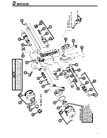
1. Remove Air Connection, Item 23, (see Page 4 Parts List) from Gun Handle.
2. Remove Plug Assembly, Item 24, (see Page 4 Parts List) from Gun Handle.
3. Insert Stem, Item 7, (with “O” Ring) of Valve Assembly into Hole from which Plug
Assembly was removed.
NoTe:
Valve Assembly does not have to be screwed in tightly; the “O” Ring at the top
of the Stem provides a complete air seal. Apply a small amount of petroleum
jelly to “O” Ring before inserting Stem into Gun Handle.
4. Rotate Valve Assembly so that the flat face of its Body, Item 11, (containing the
groove) allows clearance for inserting Air Connection, Item 1, into Hole in base of
Gun from which Air Connection (see Step 1 above) was removed.
5. Insert Air Connection, Item 1, and screw up tightly.
6. Hook up Solvent Flush Hose to Valve Assembly at D.M. Nipple, Item 17.
7. Hook up Air Hose to Air Connection, Item 1.
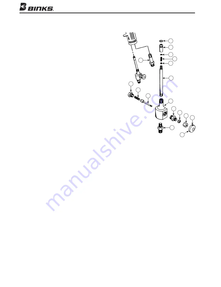
1
54-2138
AIR CONNECTION . . . . 1
2
20-3847
“O” RING . . . . . . . . . . . 1
3 54-2407 CAP . . . . . . . . . . . . . . . . 1
4
20-4544
“E” RING. . . . . . . . . . . . 1
5 54-2139 SPRING
. . . . . . . . . . . . . 1
6
20-2183
BALL, 3/16 in. dia. . . . . 1
7 54-2408 STEM. . . . . . . . . . . . . . . 1
8 102-2136 CAP . . . . . . . . . . . . . . . . 1
9 102-2142 SPRING . . . . . . . . . . . . . 1
10 102-2135 STEM
ASSEMBLY . . . . . 1
11 102-2132 BODY .. . . . . . . . . . . . . 1
12 102-2133 GLAND . . . . . . . . . . . . . 1
13 54-2419 PACKING. . . . . . . . . . . . 1
14 54-2417 CAP . . . . . . . . . . . . . . . . 1
15 20-3750
SET SCREW, 6-32 . . . . . 1
16 102-2137 BUTTON . . . . . . . . . . . . 1
17
72-792
D.M. NIPPLE,
1/8 NPT x 1/4 NPS. . . . . 1
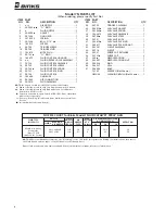
PaRTS liST
(When ordering, please specify Part No.)
iTeM PaRT
No. No.
deSCRiPTioN
qTy.
iTeM PaRT
No. No.
deSCRiPTioN
qTy.
Binks 7N Gun accessories
Binks Model 102-2138 FluSh ValVe aSSeMBly FoR Model 7N GuN
1
2
3
4
5
6
7
11
10
9
8
12
13
14 15
17
16
Summary of Contents for 7N
Page 7: ...NOTES 7 ...


