background image

EN

77-2625-R13.1  (8/2014)

4 / 12

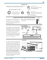
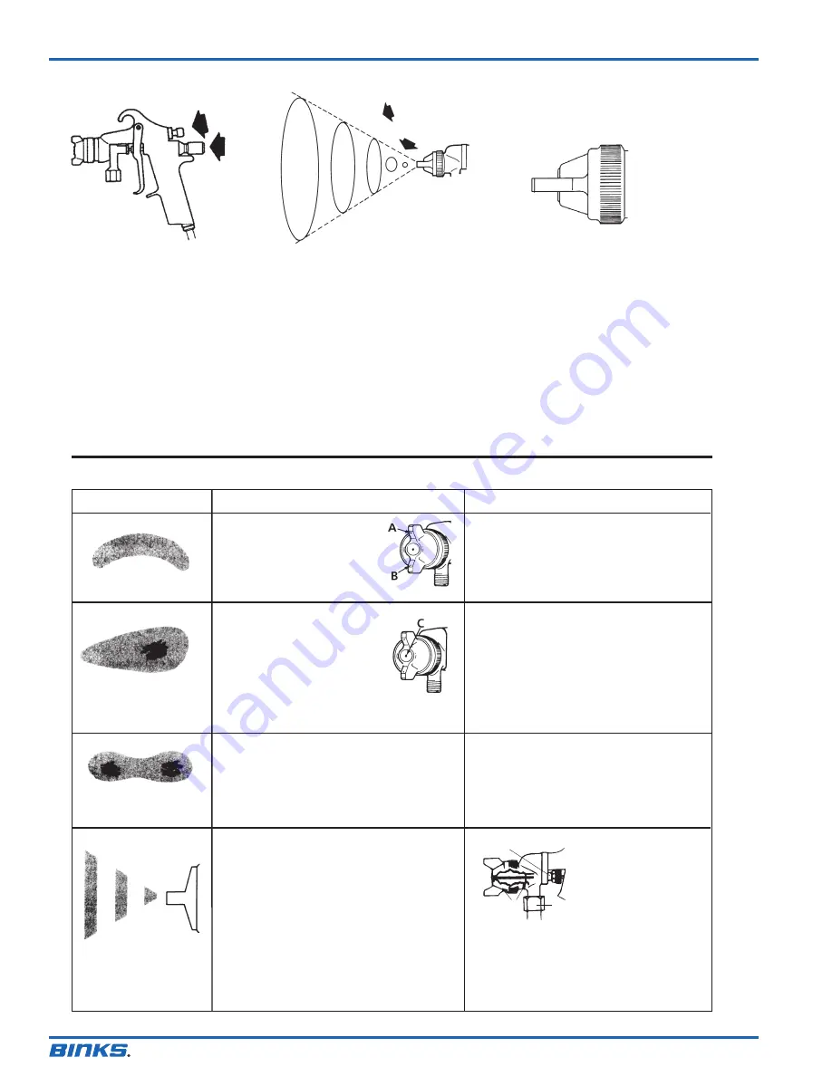
In normal operation, the wings on
the nozzle are horizontal as illus-
trated here. This provides 
a vertical fan shaped pattern which

gives maxi-
mum coverage
as the gun is
moved back
and forth par-
allel to the
surface being
finished.

Spray width adjustment: Turn clock-
wise for round, counterclockwise for fan.
Fluid control screw: Turn clockwise to
decrease flow, counterclockwise to
increase flow.
As width of spray is increased, more
material must be allowed to pass through
the gun to obtain the same coverage on
the increased area.

SIPHON SPRAYING

Set atomization pressure at approximate-
ly 50 PSI for lacquer and 60 PSI for
enamel. Test spray. If the spray is too
fine, reduce the air pressure or open fluid
control screw. If the spray is too coarse,
close the fluid control screw. Adjust the
pattern width and repeat adjustment of
spray if necessary.

PRESSURE SPRAYING

After selecting correct size fluid orifice,
set fluid pressure for desired flow. Open
atomization air and test spray. If spray is
too fine, reduce air pressure. If spray is
too coarse, raise air pressure. Adjust pat-
tern width and repeat adjustment of spray.
Keeping fluid control screw in open posi-
tion will reduce fluid needle wear.

The spray pattern of 
the Binks gun is variable
from round to flat with
all patterns in between.

Spray width

adjustment

Fluid 

control

screw

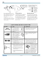
FAULTY PATTERNS AND HOW TO CORRECT THEM

PATTERN

CAUSE

CORRECTION

Dried material around the
outside of the fluid nozzle tip
at position “C” restricts the
passage of atomizing air at
one point through the center
opening of air nozzle and
results in pattern shown. 
This pattern can also be caused 
by a loose air nozzle.

Dried material in side-port
“A” restricts passage of air.
Greater flow of air from
cleaner side-port “B” forces
fan pattern in direction of
clogged side.

Dissolve material in side-ports with thinner, 
then blow gun clean. Do not poke into 
openings with metal instruments.

Remove air nozzle and wipe off fluid tip
using rag wet with thinner. Tighten air 
nozzle.

A split spray or one that is heavy on each
end of a fan pattern and weak in the mid-
dle is usually caused by:
(1) Too high an atomization air pressure 
(2) Attempting to get too wide a spray pat-

tern with thin material.

Reducing air pressure will correct cause (1).
To correct cause (2), open material control
to full position by turning to left. At the
same time, turn spray width adjustment to
right. This will reduce width of spray, but
will correct split spray pattern. 

(1) Dried out packing around material nee-

dle valve permits air to get into fluid
passageway. This results in spitting.

(2) Dirt between fluid nozzle seat and

body or loosely installed fluid nozzle
will make gun spit.

(3) A loose or defective swivel nut on

siphon cup or material hose can cause
spitting.

To correct cause (1) back
up knurled nut (E), place
two drops of machine oil
on packing, replace nut
and tighten with fingers
only. In aggravated cases,
replace packing.

To correct cause (2), remove fluid nozzle (F),
clean back of nozzle and nozzle seat in gun
body using rag wet with thinner, replace 
nozzle and draw up tightly against body.
To correct cause (3), tighten or replace 
swivel nut.

E

F

G

Summary of Contents for 95

Page 1: ...pressure for atomization is regulated at extractor fluid pressure at tank regulator see figure 3 PRESSURE FEED TANK HOOKUP For portable painting operations double regulator Air pressure for atomization and fluid supply is regulated by two individual air regulators on tank see figure 4 TYPES OF INSTALLATION SIPHON FEED CUP HOOKUP Air pressure for atomization is regulated at extractor The amount of ...

Page 2: ...RELIEF PROCEDURE Always follow the pressure relief procedure in the equipment instruction manual NOISE HAZARD You may be injured by loud noise Hearing protection may be required when using this equipment STATIC CHARGE Fluid may develop a static charge that must be dissipated through proper grounding of the equipment objects to be sprayed and all other electrically conductive objects in the dispens...

Page 3: ...pplied at air supply Atomizing pressure must be set properly to allow for the drop in air pressure between the regulator and the spray gun Achieving a fine spray finish without the use of a good oil and water extractor is virtually impossible A Binks regulator extractor serves a double pur pose It eliminates blistering and spotting by keep ing air free of oil and water and it gives precise air pre...

Page 4: ...p at position C restricts the passage of atomizing air at one point through the center opening of air nozzle and results in pattern shown This pattern can also be caused by a loose air nozzle Dried material in side port A restricts passage of air Greater flow of air from cleaner side port B forces fan pattern in direction of clogged side Dissolve material in side ports with thinner then blow gun c...

Page 5: ... thinners into the container to wash the hose and gun thoroughly and spray this through the gun until it is clean Then blow out the material hose to dry it and remove all traces of material by attaching it to the air line CLEANING GUN USED WITH PAINT CIRCULATING SYSTEM Shut off material supply and remove material hose from gun Clean gun as used with siphon cup or pressure contain er or connect qui...

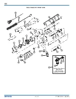
Page 6: ...6 12 43 46 42 44 1 2 3 4 5 6 7 14 15 16 17 18 15 14 19 20 21 18 9 10 11 12 13 8 24 23 22 31 30 29 28 27 26 25 45 Binks Model 95 SPRAY GUN 47 48 49 50 Optional for vitreous applications order Fluid Inlet Assembly Kit 54 4511 51 ...

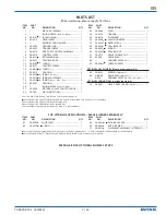
Page 7: ...5 54 3592 COPPER GASKET 1 OPTIONAL ACCESSORIES Please order separately 42 54 4213 WRENCH Optional 1 46 OMX 88 GUN BRUSH Optional 1 6 429 GUNNERS MATE 20 ea 2oz bottles 1 OPTIONAL SPRINGS Please order separately 18 54 4427 HEAVY DUTY SPRING 29 lbs 1 PARTS LIST When ordering please specify Part No FOR VITREOUS APPLICATIONS PLEASE ORDER SEPARATELY SEE PAGE 8 FOR OPTIONAL NOZZLE SETUPS ITEM PART NO NO...

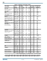
Page 8: ...659 59Bss x 251 PI 7 8 11 5 15 2 12 659 59Bss x 252 PI 7 8 11 5 15 2 6 659 59Css x 262 PI 7 3 11 0 14 7 6 659 68ss x 206 PI 6 2 9 8 13 2 15 668 ADHESIVES 63Bss x 66SD 3 PE 7 9 12 1 16 2 4 663 Waterbase white vinyl glues 67ss x 67PB PE 9 5 14 1 19 1 12 667 Solvent base neoprenes 66ss x 66SD 3 PE 7 9 12 1 16 2 10 665 contact cement 66ss x 66SDJG PE 10 4 8 9 665 66ss x 66R PE SE 4 2 RD 665 L6SS x 66S...

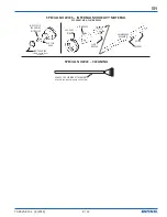
Page 9: ...E CHART AIR FLUID NOZLES SPECIAL NOZZLE CLEANING FLUID NOZZLE AIR NOZZLE 54 2065 RING 54 1583 BASE 659 NEEDLE ASSEMBLY GUIDE 54 1584 RING USED WITH 200 SERIES TIPS ONLY NOZZLE TIP 200 SERIES NITRALLOY SCREW 54 928 10 CLEANING ATTACHMENT REQUIRED FOR DEGREASING AND LUBRICATING ...

Page 10: ...EN 77 2625 R13 1 8 2014 10 12 NOTES ...

Page 11: ...EN 77 2625 R13 1 8 2014 11 12 NOTES ...

Page 12: ...national sales and customer support locations below USA Canada www binks com info finishingbrands com Tel 1 800 992 4657 Fax 1 888 246 5732 United Kingdom www finishingbrands eu info finishingbrands eu Tel 44 0 1202 571 111 Fax 44 0 1202 573 488 China www finishingbrands com cn mkt finishingbrands com cn Tel 8621 3373 0108 Fax 8621 3373 0308 Mexico www finishingbrands com mx sales finishingbrands ...

Reviews: