


EN
77-2655-R4.1 (1/2015)
4 / 16
Binks Models 95AR and 95ARV AUTOMATIC SPRAY GUNS
Typical Arrangement Diagram and Hook-up for
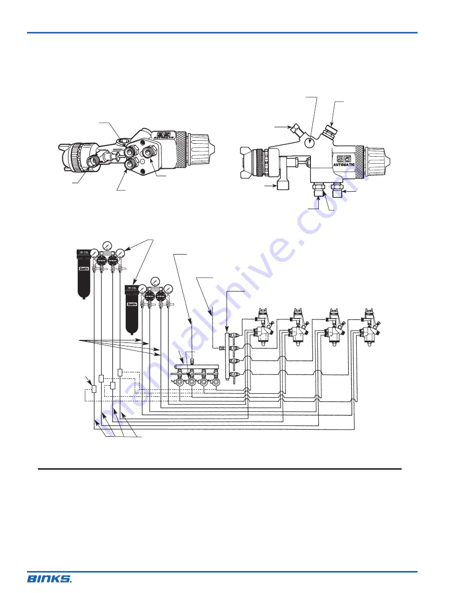
Separate Fan and Atomizing Air
(See Page 5 for Internal Modifications to Gun)
Fluid Inlet
Fan Air
Inlet
Atomizing Air Inlet
Cylinder Air
Mounting Lockscrew
Side Port
Control Assembly
(Fan Pattern
Size Control)
Cylinder Air
Inlet 1/4" NPS
Atomizing Air Inlet
1/4" NPS
Fan Air Inlet
1/4" NPS
Mounting Hole (1/2"
Dia.)
Fluid Inlet
3/8" NPS
GENERAL NOTES
1. Have at least 55-60 P.S.I. air pressure for cylinder’s
operating air. (Maximum 90 PSIG)
2. To reduce overspray and obtain maximum efficiency,
always spray with lowest possible fluid/air pressure
that produces an acceptable spray pattern.
3. The air line from gun to 3-way valve should be as
short as possible for rapid operation.
4. All air used in the gun should be dirt and moisture
free. (This is accomplished by using an oil and water
extractor).
5. Shut off all fluid and air lines to gun if gun is to
stand idle for any length of time. (This is to prevent
“build-up” or accumulation of minute leaks in the
system and turning on the gun).
Oil and Water Extractor
Regulated Cylinder Air From
Oil and Water Extractor
Regulated Fluid Inlet
Four Gun Material Manifold
3-Way
Solenoid
3-Way
Pilot
Valve
4 Gun
Air
Mani -
fold
Fan Air
For some applications each gun may require individually regulated fluid and air inlet lines.
Atomizing
Air
Hook-up Diagram 2 (editable) 12/16/11 12:31 PM Page 1


