background image

EN

77-2655-R4.1  (1/2015)

5 / 16

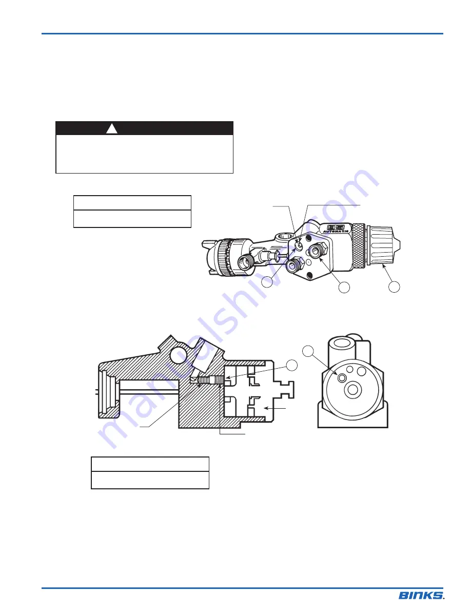
TO CHANGE FROM COMBINED FAN AND ATOMIZING AIR

TO SEPARATE FAN AND ATOMIZING AIR

1.   Unscrew ratchet housing assembly (28) and remove 

material needle (22) and attached parts (23, 24, 25) 
(see assembly drawing page 10).

2.   Remove piston assembly (18) by injecting low  

pressure air into cylinder air port (A).

3.    With 5/32" allen wrench, remove plug (16) from hole 

(B) on inside of cylinder.

4.   Insert set screw (50) into position as shown in side 

cut-away. (Set screw is packaged loose.)

5.   Re-install plug (16).
6.   Re-install piston (20), 2 springs (26, 27), material 

needle (22) and ratchet housing assembly (28). (See 
assembly drawing page 10).

7.   Remove plug (47) from the fan air port (C).
8.   Install fitting (36) into port (C). (Fitting is  

packaged loose.)

Plug (47)

Remove and install 

D.M. Nipple (36)

Fan Air Inlet 

(Optional)

A

C

28

B

B

View A

Set Screw

(16)

Set Screw (50)

Side Cut-Away

View A

  WARNING

Use of excessive pressure will cause piston to exit gun 

body at high velocity, possibly resulting in personal injury 

or damage to spray gun components. When removing the 

piston, aim back of gun in a safe direction and do not use 

excessive air pressure.

!

NOTE

Double male nipple (36) shipped loose 

in a separate bag.

NOTE

Set screw (50) shipped loose in a sepa-

rate bag.

Summary of Contents for 95AR

Page 1: ...l and waterborne coatings It is also pneumatically activated for application with recipro cating rotary spindle machines and in stationary gun set ups Exceptionally rugged in construction the Binks Models 95AR and 95ARV automatic guns are built to stand up under hard continuous use However like any other fine precision instruments their most efficient operation depends on a knowledge of their cons...

Page 2: ...RELIEF PROCEDURE Always follow the pressure relief procedure in the equipment instruction manual NOISE HAZARD You may be injured by loud noise Hearing protection may be required when using this equipment STATIC CHARGE Fluid may develop a static charge that must be dissipated through proper grounding of the equipment objects to be sprayed and all other electrically conductive objects in the dispens...

Page 3: ...ort Control Assembly Fan Pattern Control Fluid Needle Stroke Adjustment Cylinder Air Inlet 1 4 NPS Atomizing Air Inlet 1 4 NPS Mounting Hole 1 2 Dia Fluid Inlet 3 8 NPS Oil and Water Extractor Regulated Cylinder Air From Oil and Water Extractor Regulated Fluid Inlet Four Gun Material Manifold 3 Way Solenoid Four Gun Air Manifold Combined Fan and At omizing Air 95A or 95AV Auto matic Gun For some a...

Page 4: ...th lowest possible fluid air pressure that produces an acceptable spray pattern 3 The air line from gun to 3 way valve should be as short as possible for rapid operation 4 All air used in the gun should be dirt and moisture free This is accomplished by using an oil and water extractor 5 Shut off all fluid and air lines to gun if gun is to stand idle for any length of time This is to prevent build ...

Page 5: ...nstall piston 20 2 springs 26 27 material needle 22 and ratchet housing assembly 28 See assembly drawing page 10 7 Remove plug 47 from the fan air port C 8 Install fitting 36 into port C Fitting is packaged loose Plug 47 Remove and install D M Nipple 36 Fan Air Inlet Optional A C 28 B B View A Set Screw 16 Set Screw 50 Side Cut Away View A WARNING Use of excessive pressure will cause piston to exi...

Page 6: ...erial flow rate If necessary fluid flow can also be adjusted by adjusting the amount of needle travel This is done by loosening lock nut 29 and adjusting control knob 30 until the correct needle travel is achieved ADJUSTING AIR AND FLUID TIMING A 1 16 gap between the air piston assembly 18 and needle body 24 should be maintained see figure 1 This will create needle motion that will allow adequate ...

Page 7: ...ack into liquid form which prevents escape of VOC s into the atmosphere 2 Place spray gun in a washer type container This sys tem must totally enclose the spray gun cups nozzles and other parts during washing rinsing and draining cycles This type of unit must be able to flush solvent through the gun without releasing any VOC vapors into the atmosphere Additionally open containers for stor age or d...

Page 8: ...3 20 0 14 0 763A 63CSS x 63PR PE 9 5 15 5 19 5 18 0 763A 65SS x 63PR PE 11 0 16 5 22 0 15 0 765 66SS x 66SD SE 7 9 12 1 11 0 765 66SS x 66SK SE 11 0 15 2 19 5 13 0 765 63CSS x 200 PI 3 1 5 2 6 4 12 0 763A 63BSS x 21MD 3 PE 11 6 16 6 22 2 16 0 763A 66SS x 21MD 2 PE 12 5 18 3 24 4 13 0 765 67SS x 206 PI 6 0 9 5 13 0 15 0 767 68SS x 201 PI 4 6 6 8 9 1 11 0 768 68SS x 101 PI 4 6 6 8 9 1 11 0 768 66SS ...

Page 9: ... Carbite Air Nitralloy Air Nozzle Nozzle No 59ASS 59BSS 59CSS 63ASS 63BSS 63CSS 65SS 66SS 67SS 68SS Orifice Size 171 218 281 040 046 052 059 070 086 110 STANDARD PART NUMBERS for 95AR GUN with Fluid Nozzles and Air Caps and Needles Included COMPATIBLE 95ARV GUN NOZZLE SET UPS 95AR Nozzle set ups shown on pages 12 13 TUNGSTEN CARBITE CARBITE TIP CARBITE TIP CARBITE TIP FLUID NOZZLE FLUID NOZZLE FLU...

Page 10: ...d 50 are for installations requiring separate fan and atomizing air control Items are packaged loose See pg 5 1 2 3 4 5 6 7 8 9 10 12 13 14 15 16 50 48 49 51 18 17 19 20 21 27 58 26 25 24 39 40 38 44 59 60 60 52 46 53 45 47 36 36 29 42 43 30 28 31 41 22 11 23 37 34 35 32 33 60 54 55 56 57 95ARV FLUID INLET ...

Page 11: ...R Gun 1 40 54 4265 NEEDLE SEAL 95AR Gun 1 41 54 4266 SEAL BACKUP 95AR Gun 1 42 54 4267 SPRING 95AR Gun 1 43 54 4263 PACKING NUT 95AR Gun 1 44 57 13 DOUBLE MALE NIPPLE 1 4 NPT x 1 4 NPS 1 45 54 3716 AIR VALVE GLAND ASSEMBLY 1 46 20 3859 O RING 1 47 54 3986 PLUG 1 8 27 NPT 1 48 54 4213 WRENCH Optional 1 49 82 469 GUN BRUSH 1 50 20 2141 SET SCREW 1 4 20 UNC 1 51 54 3871 GUNNERS MATE 1 52 54 4270 NEED...

Page 12: ...prox 2 4 2 4 1 2 Diameter Hole for Gun Mounting Bracket COMPATIBLE 95AR GUN NOZZLE SET UPS STAINLESS STAINLESS STAINLESS STAINLESS STEEL FLUID STEEL FLUID STEEL FLUID STEEL FLUID NOZZLE NOZZLE PART NEEDLE NEEDLE PART COMPATIBLE AIR CAP DESIGNATION NUMBER DESIGNATION NUMBER AIR CAPS PART NUMBER 62SS 45 6201 762 47 760 63P 46 6000 63PB 46 6002 63PR 46 6079 66PH 46 6016 66SD 46 6020 66SD 3 46 6092 66...

Page 13: ...14 66PH 46 6016 66R 46 6041 66S 46 6018 66SD 46 6020 66SD 3 46 6092 66SK 46 6082 67SS 45 6701 767 47 766 67PB 46 6101 67PD 46 6028 706 46 2013 Tip and 54 372 Base 709SS 46 2020 Tip and 54 372 Base 713 46 2025 Tip and 54 372 Base 797 46 156 Tip and 54 372 Base 68SS 45 6801 768 47 768 68PB 46 6032 201 46 2201 Tip and 54 1583 Base 54 1584 Ring 206 46 2206 Tip and 54 1583 Base 54 1584 Ring 706 46 2013...

Page 14: ...EN 77 2655 R4 1 1 2015 14 16 NOTES ...

Page 15: ...EN 77 2655 R4 1 1 2015 15 16 NOTES ...

Page 16: ...ational sales and customer support locations below USA Canada www binks com info finishingbrands com Tel 1 800 992 4657 Fax 1 888 246 5732 United Kingdom www finishingbrands eu info finishingbrands eu Tel 44 0 1202 571 111 Fax 44 0 1202 573 488 China www finishingbrands com cn mkt finishingbrands com cn Tel 8621 3373 0108 Fax 8621 3373 0308 Mexico www finishingbrands com mx sales finishingbrands c...

Reviews: