
3
1. Connect your high-pressure airless fluid hose to the
gun fluid inlet and tighten securely.
2. Connect your air hose to the gun air connection and
tighten securely.
3. Using the control knob of the fluid regulator, set the
fluid pressure at the gun’s lower end of the pressure
range. A typical starting fluid pressure is 350 psi.
Actual starting pressure points may be higher or lower
than 350 psi and depend on the setup including the
type of pump used, the type of material sprayed, and
the spray gun itself.
4. Using the control knob on the air regulator, set the air
pressure at zero.
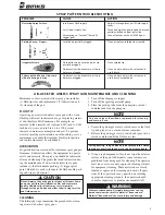
5. To test the spraying pattern, spray a piece of wood or
cardboard with a fast pass about one foot away from
the piece. The results of the test will allow you to
determine the uniformity of the particle size and
spraying pattern.
6. If the spraying pattern develops tails or is not uniform,
gradually increase the air pressure as necessary to
develop a uniform spraying pattern. Typically, 10 psi
air pressure is adequate. The air is used to assist the
atomization of the coating.
7. If the quality of spray is acceptable, begin spraying.
If the spraying rate is too slow to keep up with the
production line speed, or if the quantity of material
sprayed is inadequate for acceptable coverage, gradu-
ally increase the fluid pressure in 50 psi increments
using the fluid regulator control knob. However, note
that as the fluid pressure increases, more air is needed
to eliminate the tails.
Consistency in spraying can be increased across spray
gun operators and similar spraying jobs by developing
pressure standardization charts. Repeat step 6 until the
required material coverage and spraying speed are
achieved. If the maximum fluid pressure is reached
before the required material coverage and spraying speed
are achieved, you may need to switch to a larger fluid tip.
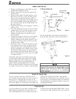
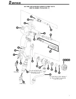
tYPicaL HooK-UP
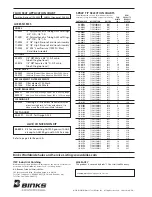
Fan pattern adjustment: turn knob counterclockwise to
increase pattern; clockwise to decrease pattern (Fig. 2).
SPRaY GUn Set-UP
Pump
Regulator
Regulator
Air
Air
Air
Fluid
Fluid Filter
Gun
Oil and Water
Extractor
figure 1
Fan Control
Knob
figure 2
fLUid tiP SeLection
Factors to consider in selecting a fluid tip for an air-
assisted airless spray gun include (1) the size of the parts
being sprayed; (2) the production line speed; (3) the
material flow rate and film thickness; (4) the viscosity of
the material applied; (5) the type of material applied; and
(6) the quality of atomization of the coating required.
The selection of a fluid tip necessary to perform a specif-
ic spraying job is best determined through a combination
of experimentation and expert advice from your material
and equipment suppliers.
fLUid HoSeS
Air-assisted airless spray guns operate at fluid pressures
higher than operating pressures of air spray guns. As a
result, when operating an air-assisted airless spray gun, it
is critical to select the appropriate fluid hose that is rated
for the pressure range at which the airless gun is operated.
Air
In
note
fan adjustment feature requires approximately 25 psi or
higher of air inlet pressure. this is recommended for fluid
pressures lower than 500 psi. Higher fluid pressure
requires higher air inlet pressures to accommodate
pattern adjustment.


