


4
TROUBLESHOOTING DEFECTIVE SPRAY PATTERNS
The following procedure summarizes the steps that an
operator must immediately take when the first signs of a
defective spray pattern emerge.
1. Check the external portion of the fluid tip for material
buildup. If buildup has occurred, secure the gun trig-
ger safety switch and clean the gun fluid tip with a
non-metal soft brush.
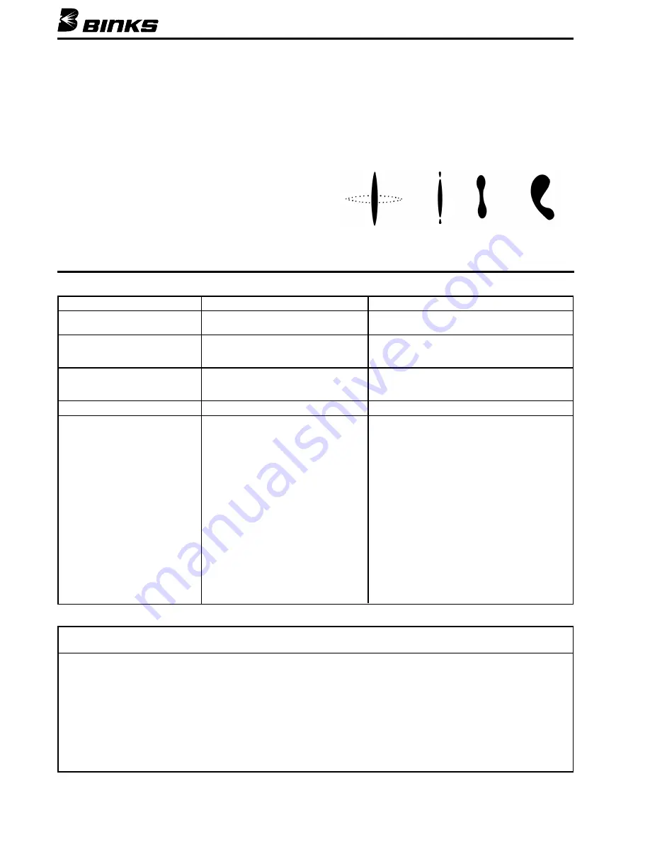
2. If the spray pattern exhibits signs of tails at the top or
bottom ends of the pattern, increase the air pressure
gradually until the tails disappear.
3. If increasing air pressure does not dissipate the tails,
the fluid tip may be worn and may need to be
replaced. Another sign of the need to replace a worn
tip is a gradual decline in spraying pattern width.
4. If cleaning or replacing the fluid tip does not dissipate
the tails; the spraying defect is most likely due to the
material temperature and/or viscosity.
5. If pattern pulsation or blinking occurs, check the pres-
sure regulators, all downstream regulators, and the
pump. These may require further adjustment or even
repairs.
Figure 3
Correct
Pattern
Tails
Hour
Glass
Distorted
Pattern
PROBLEM
CAUSE
ACTION
Fluid leaking from the back
Worn seal or needle shaft.
Replace needle packing cartridge (8).
of seal cartridge assembly (8)
Fluid leaking from the front
Needle ball worn or damaged.
Replace needle packing cartridge (8).
of the gun
Worn seat assembly.
Replace fluid seat (4).
Fluid in air passages
Spray tip seal leaking.
Tighten retaining ring (1)
Replace carbide tip assembly (3).
Leaking around fluid seat.
Tighten or replace fluid seat (4).
Slow fluid shut off
Fluid buildup on cartridge assembly.
Clean or replace cartridge assembly (8).
No fluid output when triggered
Tip orifice plugged.
Turn off fluid supply. Relieve pressure into a
closed-grounded container.
Engage trigger safety.
Remove tip guard assembly (1) and air cap (2)
and the carbide tip (3).
Clean or replace carbide tip assembly (3).
Collet on needle has slipped.
Turn off fluid supply. Relieve pressure into a
closed-grounded container.
Remove trigger (20). Remove needle packing
cartridge (8). Loosen collet and move until
the needle is flush with the rear of the collet.
Tighten collet.
Fluid filter or fluid hose plugged.
Turn off fluid supply. Relieve pressure into a
closed-grounded container. Turn off air supply
to pump and relieve fluid pressure with bypass
valve. Engage trigger safety. Very slowly loosen
the hose connection at the gun to relieve any
pressure in hose.
Remove hose and clear
obstruction.
GENERAL TROUBLESHOOTING
IMPORTANT REGULATORY NOTE
The AA-4000 Air-Assisted H.V.L.P. hand spray gun combines the proven efficiency of the Binks compliant spray guns with
air-assisted atomization to yield a reliable, carefully engineered compliant spray gun. With 25' of 5/16" I.D. air hose and
regulator set at only 20 p.s.i. the compliant air cap registers 10 p.s.i. of atomization air to shape and soften the spray
pattern. The AA-4000 air-assisted H.V.L.P. gun operates at high transfer efficiencies and fully complies with all govern-
ment regulations for H.V.L.P. spray guns.
Max. Fluid Input:
4000 p.s.i.
Max. static air pressure at regulator with 25' of hose to inlet:
20 p.s.i.
Max. Dynamic Gun Inlet Air Pressure:
15 p.s.i.
Gun Body:
Forged Aluminum Alloy
Fluid Path:
Stainless Steel and Tungsten Carbide


