background image

3

OPERATION and MAINTENANCE INSTRUCTIONS for M1-G HVLP SPRAY GUN

SPRAY GUN CLEANING INSTRUCTIONS

In certain states, spraying solvents which contain Volatile
Organic Compounds (VOC) into the atmosphere when
cleaning a spray gun is now prohibited.

In order to comply with these new air quality laws Binks
recommends one of the following two methods to clean
your spray finishing equipment:

1.

Spray solvent through the gun into a 

closed system

.

An enclosed unit or spray gun cleaning station con-
denses solvent vapors back into liquid form which
prevents escape of VOC’s into the atmosphere.

2.

Place spray gun in a washer type cleaner. This 
system must totally enclose the spray gun, cups, noz-
zles and other parts during washing, rinsing and
draining cycles. This type of unit must be able to

flush solvent through the gun without releasing any
VOC vapors into the atmosphere.

Additionally, open containers for storage or disposal
of solvent or solvent-containing cloth or paper used for
surface preparation and clean-up may not be used.
Containers shall be nonabsorbent.

CLEANING GUN AND GRAVITY FEED CUP

Remove the cup cover and drain unused material from
cup. Carefully rinse cup with solvent. Place clean solvent
into the cup and spray this through the gun until it is clean.
Remove and clean the cup if necessary. Blow air through
the gun to dry it. (Refer to Service Bulletin SBBI-4-043 for
cleaning instructions when using cup liners.)

Your new M1-G HVLP Spray Gun is exceptionally rugged
in construction and is built to stand up under hard, continu-
ous use. However, like any other fine precision instrument,
its most efficient operation depends on a knowledge of its
construction, operation and maintenance. Properly handled
and cared for, it will produce beautiful, uniform finishing
results long after other spray guns have worn out.

IMPORTANT:

Before removing any components from the

spray gun, shut off air pressure and drain material from the
paint cup.

SETUP FOR SPRAYING

CONNECTING GUN TO AIR HOSE

Air should be supplied by a suitable length of 5/16" diameter
air hose fitted with a 1/4 NPS(f) connection at gun end. For
hose lengths over 50', use 3/8" hose.

CONNECTING GRAVITY FEED CUP TO GUN
(Figure 1)

Screw the cup into the spray gun fluid inlet.

Fig. 1

OPERATING THE M1-G HVLP SPRAY GUN

CONTROLLING THE MATERIAL FLOW

Correct fluid nozzle size should be selected for proper
material flow rate. The material valve control knob (19)
may be used to restrict the material needle valve opening
and reduce the material flow as necessary.

CONTROLLING THE  FAN  SPRAY

The fan spray is controlled by means of the side port
control assembly (9). Turning this control clockwise until
it is closed will give a round spray. Turning it counter-
clockwise will widen the spray into a fan shape. The fan
spray can be turned anywhere through 360° by position-
ing the air cap (2) relative to the gun. To affect this,
loosen retainer ring, position nozzle, then tighten retainer
ring.

TROUBLE SHOOTING

FAULTY SPRAY

A faulty spray is often caused by improper cleaning,
resulting is dried materials around the material nozzle tip
or in the air nozzle. Soak these parts in thinners to soften
the dried material and remove with brush or cloth.

If either the air cap (2) or fluid nozzle (3) are damaged,
these parts must be replaced before perfect spray can be
obtained.

INTERMITTENT SPRAY

Fluttering spray is caused by either insufficient material
in the gravity feed cup or a clogged fluid passage. If the
fluid passage is clogged, drain material from the paint
cup and remove the cup and fluid nozzle. Clean the fluid
passage with solvent and reassemble.

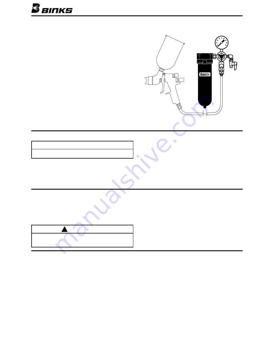
Gravity Feed Cup

Air

Extractor

NOTE

All numbers in parentheses ( ) refer to item numbers in

Assembly Drawing on Page 6.

CAUTION

Never use metal instruments to clean the air or material
nozzles. These parts are carefully machined and any damage
to them will cause faulty spray.

!

Summary of Contents for M1-G HVLP

Page 1: ...gh vol ume low pressure air spray gun The Binks M1 G HVLP Gravity Feed Spray Gun includes a metal paint cup with drip proof cover To obtain optimum performance from your new M1 G HVLP Gravity Feed Spray Gun read all instructions care fully PACKAGE CONTENTS Please note your Binks M1 G HVLP Gravity Feed Spray Gun package was shipped with the following con tents If anything in the following list is m...

Page 2: ...ounding or sparks can cause a hazardous condition and result in fire explosion or electric shock and other serious injury FIRE AND EXPLOSION HAZARD Never use 1 1 1 trichloroethane methylene chloride other halogenated hydrocarbon solvents or fluids containing such solvents in equipment with aluminum wetted parts Such use could result in a serious chemical reaction with the possibility of explosion ...

Page 3: ...Before removing any components from the spray gun shut off air pressure and drain material from the paint cup SETUP FOR SPRAYING CONNECTING GUN TO AIR HOSE Air should be supplied by a suitable length of 5 16 diameter air hose fitted with a 1 4 NPS f connection at gun end For hose lengths over 50 use 3 8 hose CONNECTING GRAVITY FEED CUP TO GUN Figure 1 Screw the cup into the spray gun fluid inlet F...

Page 4: ...00 Dia 2 5 mm 905P 54 4394 909F 111 Dia 2 8 mm 54 4395 FEATHERING NOZZLES For applications requiring more gradual Material Valve opening metering control of fluid flow is obtained with Gun Trigger The 97P or 907P Air Nozzles may be used but will cause a significant reduction in fluid flow rate Optimum setup for fine automotive spray is 94 x 93P BLUE MAX fine finish nozzles Retaining ring attached ...

Page 5: ...0 14 0 9 0 5 0 21 0 11 0 7 0 27 0 12 0 9 0 30 0 13 0 10 0 33 0 LVLP AIR NOZZLE 93P NOZZLE NOZZLE REGULATOR ATOMIZING ATOMIZING GUN INLET PRESSURE AIR FLOW SCFM PRESSURE PSI PRESSURE PSI PSI 5 5 3 0 8 0 10 0 7 0 5 0 11 5 14 0 8 0 7 0 14 5 18 0 9 5 9 0 17 0 22 5 10 0 10 0 18 0 24 0 LVLP AIR NOZZLES 92P NOZZLE NOZZLE REGULATOR ATOMIZING ATOMIZING GUN INLET PRESSURE AIR FLOW SCFM PRESSURE PSI PRESSURE...

Page 6: ... 13 14 11 28 30 31 26 15 10 16 13 12 17 19 16 18 24 21 20 27 29 REFER TO SERVICE BULLETIN SBBI 4 043 FOR Warnings and cautions for cup assembly 54 4720 Assembly instructions for the liner not shown Cleaning instructions for the cup assembly when used with or without the liner 32 25 ...

Page 7: ...GFC 404 DISPOSABLE LID ASSEMBLY Quantity 2 supplied 54 4720 26 KGP 13 CUP GASKET Blue 1 27 54 3918 WRENCH Optional 1 28 82 469 GUN BRUSH Round 1 29 KGP 5 FILTER 30 192219 PLASTIC COATED GUN HOOK 1 31 54 3871 GUNNER S MATE 1 32 82 221 CLEANING BRUSH Flat 1 33 OMX 70 DISPOSABLE LINER Not Shown Refer to Service Bulletin SBBI 4 043 PARTS LIST When ordering please specify PART NO See Air and Fluid Nozz...

Page 8: ... inches depending on material and atomizing pressure The material deposited should always be even and wet Lap each stroke over the preceding stroke to obtain a uni form finish Oil and Water Extractor is important Achieving a fine spray finish without the use of a good oil and water extractor is virtually impossible A Regulator Extractor serves a double purpose It eliminates blistering and spotting...

Page 9: ...t the gun is being operated within the limits of applicable rules AIR NOZZLE TEST GAUGE ASSEMBLY 54 3935 for 95P 97P 95AP and 97AP Nozzles 54 3908 for 900 Series Nozzles 54 4345 for 90P Air Nozzle 54 4356 for 93P Air Nozzle 54 3902 for 92P Air Nozzle 54 4066 for 94P Air Nozzle 54 4566 for 96G Air Nozzle ACCESSORIES When ordering please specify PART NO Part No Description 54 4350 Gun Stand 54 4352 ...

Page 10: ...10 NOTES ...

Page 11: ...NOTES 11 ...

Page 12: ... Canada Technical Service Office 195 Internationale Blvd Glendale Heights IL 60139 Toll Free Telephone 1 888 992 4657 U S A and Canada only Toll Free Fax 1 888 246 5732 Binks Worldwide Sales and Service Listing www binks com WARRANTY This product is covered by Binks 1 Year Limited Warranty 77 2650R 7 Revisions P1 Deleted reference air nozzle availability P4 Added Fluid Needle 54 4382 reference to ...

Reviews: