EN - 30
13 Appendix
BRS-LCi PLC
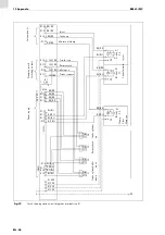
Fig. 19
Torch cleaning station circuit diagram—terminal strip X1
Pr
o
ximit
y switc
h
Swit
ch
ing outputs
Solen
o
id coils
Po
w
er
s
up
p
ly
St
ro
ke
c
yl
in
d
er
Str
o
ke
cylin
d
er
Collet
Collet open
Rotary check
Ro
ta
ry
c
he
ck
Stroke is down
Stroke is up
Motor on/clamp
Stroke up
In
je
ct
Inject
St
ro
ke
f
o
rw
a
rd
Motor on
Clam
p
Cl
o
se
open
up
do
wn
-S1
-S2
-S3
-S
4
-Y
4
-Y
1
-Y
2
BL/BU
BL/BU
BL/BU
BL/BU
BR/BR
BR/BR
BR/BR
BR/BR
BR/BR
BR/BR
BR/BR
BR/BR
SW/BK
SW/BK
SW/BK
SW/BK
BL/BU
BL/BU
BL/BU
BL/BU
-X1.3PE
-X1.2PE
-X1.1PE
-X1.4PE
-X1.10
-X1.9
-X1.8
-X1.7
-X1.6
-X1.5
-X1.13
-X1.12
-X1.11
-X1.22
-X1.21
-X1.20
-X1.19
-X1.18
-X1.17
-X1.16
-X1.15
-X1.14
-X1.23
-X1.24
BR/BR
BR/BR
BR/BR
BL/BU
BL/BU
BL/BU
PE
PE
PE
A1
A1
A1
A2
A2
A2
-D
-D
-D
PE
24
V
D
C
GND
GND
-R1
2k2
1
2
Summary of Contents for BRS-LCi SPS
Page 4: ...DE 4 1 Identifikation BRS LCi SPS ...
Page 34: ...EN 4 1 Identification BRS LCi PLC ...
Page 64: ...FR 4 1 Identification BRS LCi API ...
Page 94: ...ES 4 1 Identificación BRS LCi PLC ...
Page 123: ...BRS LCi PLC Notas ES 33 Notas ...


