BRS-LCi PLC
13 Appendix
EN - 31
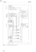
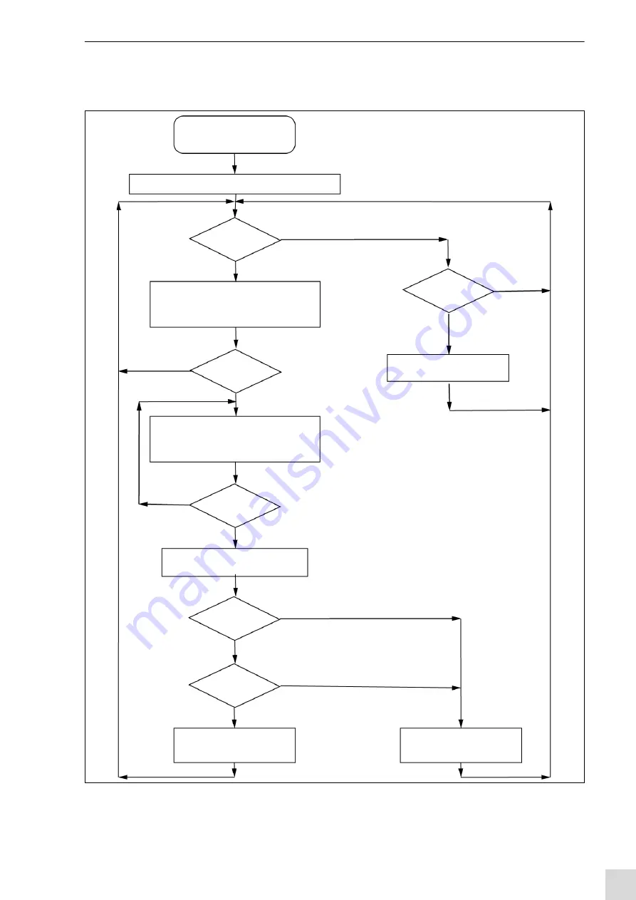
13.2 PLC control system flow chart
Fig. 20
PLC control system flow chart
Program start
(voltage on)
Internal initialization, reset error, Ready = 1
Start?
Yes
No
Reset?
Reset error, Ready = 1
Reset error, Ready = 0
Clamping valve = 1
Stroke valve = 1
Cycle timeout: Start timer
Cycle timeout: Stop timer
Clamping valve = 0
Stroke valve = 0
Clamping valve = 1
Stroke valve = 0
No
No
No
No
Yes
Yes
Yes
Yes
No
Yes
Ready = 1
Error = 0
Reset the clamp
Ready = 0, Error = 1
Set timeout cycle
Rotary check ok?
(adjustable)
Cycle
monitoring ok?
Timer
Stroke delay
ready?
Ready = 0
(delay via timer for lift up delay)
Is start still pending?
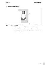
Summary of Contents for BRS-LCi SPS
Page 4: ...DE 4 1 Identifikation BRS LCi SPS ...
Page 34: ...EN 4 1 Identification BRS LCi PLC ...
Page 64: ...FR 4 1 Identification BRS LCi API ...
Page 94: ...ES 4 1 Identificación BRS LCi PLC ...
Page 123: ...BRS LCi PLC Notas ES 33 Notas ...

