Gewächshausheizung
Frosty 2500 / Frosty 4500
12
a) The following parts are required to connect the apparatus:
- Customary liquefied gas cylinder 5 kg or 11 kg
- Preset pressure regulator (conforming to the standard and certified) to match the specific
cylinder, with a gas flow rate of at least 1.0 kg/h
The supplied pressure regulator is not designed for commercial use.
- Hose (conforming to standard and certified) of adequate length (approx. 80 cm), type as per
national specification.
- Leak detection spray
- Spanners size 14 and 17
b) Connecting the apparatus:
1. Screw the union nut of the pressure regulator into the cylinder valve thread, anticlockwise
and by hand. Do not use tools since these may damage the cylinder valve seal and cause
leakage.
2. Connect the hose to the pressure regulator outlet thread anticlockwise, using a suitable
SW 17 spanner. A second suitable spanner must in this respect be used on the pressure
regulator flats to prevent the latter from turning and avoid undue torque application. Sealing is
ensured by tightening the connection, using the tool described above.
3. The other end of the hose is screwed to the threaded connecting nozzle of the apparatus.
Counter using a second SW 14 spanner on the flats of the threaded connection nozzle. The
hose must be secured if connected via a hose barb.
4. Check all connections for leaks – with cylinder valve open and gas cock closed. Tightness is
ensured if no bubbles appear.
5. Initial operation
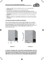
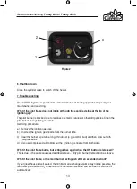
1. Using the controls (Figure 2, position 3), set the continuously adjustable thermostat to the
desired temperature.
Thermostat adjustable range
The selectable temperature range is between 2°C and 25°C.
Adjustment is continuous.
To prevent e.g. frost in the greenhouse, the thermostat should be set in the lower third of the
arrow indicator.
2. The temperature sensor, that is being mounted to the bottom edge of the rear panel, has to
be folded outwards. Thus the temperature outside the device can be taken.
3. Open the cylinder valve.
4. Press down the Start key (Figure 2, position 1) to the end stop. The pilot flame and main
burner are ignited by pressing the piezo element (Figure 2, position 2) once or twice. Keep
pressing down the Start key for about another 15 seconds after the gas ignites to allow the
thermo element to reach the necessary temperature.
Figure 2
6. Shutting down
Close the cylinder valve to switch off the heater.
7. Troubleshooting
Only CORGI registered gas dealers or manufacturers of heating apparatus may carry out
maintenance and servicing.
What if the pilot flame does not ignite although the spark is visible at the tip of the
ignition gap?
The pilot burner is blocked due to residues of small creatures or other dirt particles. Clean the
pilot burner and ignition gas nozzle.
Servicing procedure:
a) Remove the ignition gas hose
b) Unscrew the ignition gas nozzle from the burner tube
c) Clear the burner pipe with a long, thin object (e.g. a cotton bud) and then blow out with
compressed air.
d) Also use compressed air to blow out the ignition gas nozzle from both sides.
What if the pilot flame burns, but extinguishes again when the ON button is released?
This is due to the same cause as described above – dirty pilot burner; remediation as above.
What if the pilot flame, or the main burner, extinguish after an extended period?
If your greenhouse is well sealed, the minimum air exchange volume may not be possible, the
maximum permissible CO
2
concentration is therefore exceeded and the device switches off
automatically.
Over-concentration of CO
2
can be avoided as described below:
1
3
2

