8
1.4 Installation
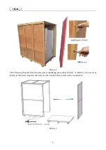
a. Remove all the packing materials
b. Check the surface of main body to make sure there is no scratch, deformation or foreign bodies
c. Confirm the complement of accessories according to the packing list
d. Before removing the packing material, move the entire equipment to the place where it is going to
be installed
The base stand will be packed at back of main body, please take it out before installation.
DO NOT INVERT, DISASSEMBLE OR TILT THE CABINET during transportation.
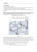
e. Assemble the base stand with main body as shown in the picture
Please assembled base stand refer to Picture 4
Picture 4
Removing Hexagon cylinder head bolt on both side lateral brace and T frame, the bottom of T frame,
assemble referring to the picture, fasten the screw and Cap nut on the both side of base stand.
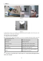
Foot height can be adjusted. Clockwise rotation of feet, when feet height is less than casters, the
cabinet can be (or base stand) moved; anticlockwise rotation of feet, when feet height is greater than
casters, then play a fixed role in preventing the cabinet (or base stand) from moving.
If you have any questions please contact engineers for commissioning
f. connecting main body and base stand
Please connect main body and base stand refer to Picture 5
Leveling feet
Caster
Hexagon socket head cap screws
M10*55/flat washer 10/spring washer 10

