background image

Microbiological Safety Cabinet

BSC-2FA2-HA

User Manual

BIOBASE GROUP

Version 2021.09

Summary of Contents for BSC-2FA2-HA

Page 1: ...Microbiological Safety Cabinet BSC 2FA2 HA User Manual BIOBASE GROUP Version 2021 09...

Page 2: ......

Page 3: ...tructions for Operation before operating this unit to assure proper operation After reading these documents be sure to store them securely together with the Warranty at a hand place for future referen...

Page 4: ...ct Concept 15 4 1 2 Application Range 15 4 1 3 Working theory Air flow pattern and protected area 15 4 1 4 Protected objects 15 4 1 5 Technical parameters 16 4 1 6 Performance Index 16 4 2 Product str...

Page 5: ...4 4 6 Methods and procedures for disinfection 24 4 7 Replacement parts list 27 4 8 Wiring diagram 28 5 Trouble shooting and Labels 29 5 1 Common faults solution 29 5 1 1 Warning and reminder 29 5 1 2...

Page 6: ...polluting samples move to high polluting samples Movement of items should also follow the principles of slow moving Samples placed in parallel Samples should be placed in the cabinet parallel to avoi...

Page 7: ...as escapes during the whole process The maximum storage period is one year If the period is more than one year performance test should be done In transportation process should take appropriate protect...

Page 8: ...person can operate in the cabinet In this way we can reduce harm out of front window trouble When the equipment is repaired or scrapped The internal parts can t be thrown about because of biological...

Page 9: ...After the expiration of warranty our company is also responsible for repairs but the corresponding maintenance cost should be charged 4 Lifetime of Microbiological Safety Cabinet is 8 years from produ...

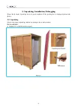
Page 10: ...firstly check if packing box is in good condition If the packing box is damaged please take photos 3 1 Unpacking Choose the proper unpacking method according to the actual situation For wooden box 1...

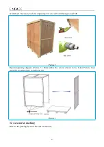
Page 11: ...drill with hexagon dead M8 Picture2 Rapid unpacking diagram Picture 3 Disassemble the screws shown in the below Picture then move the wooden pieces to right and left Picture 3 3 2 Accessories checking...

Page 12: ...e location for the cabinet Microbiological Safety Cabinet should be placed in airflow protected area Front window operation door shouldn t be against over door or window but far away from Ventilation...

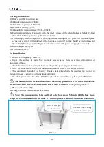
Page 13: ...there is scratch deformation or uncorrelated things c Check the attachment and information according to the packaging list in instruction d Move the whole device to the final installation location wh...

Page 14: ...t is recommended to use an elevator Refer to Picture 5 to connect base stand and main body Picture5 Take out the M10 20 Hexagon socket head screws Flat washer 10 Spring washer 10 from the accessory bo...

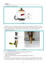
Page 15: ...casters at the same time can makes cabinet stable i Installation of Drain valve 1 Drain valve connecter 2 Shim Inner diameter outer diameter thickness 20 28 2mm 3 Safety cabinet bottom installation ho...

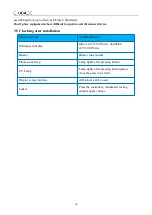
Page 16: ...king Items Normal situation Wind speed display Inflow 0 53 0 025 m s downflow 0 33 0 025 m s Blower Blower runs normal Fluorescent lamp Lamp lights after pressing button UV Lamp Lamp lights after pres...

Page 17: ...onuclide suitable exhaust hood in function have to be linked 4 1 2 Application Range Microbiological Safety Cabinet is necessary equipment in the laboratory in the search of microbiology biomedical DN...

Page 18: ...ation area needs to load the total load power of is 230V 3 0A 2 The Company reserves the right to change the design of product we will change design of product without prior notice 4 1 6 Performance I...

Page 19: ...e parts and non metallic shell in the AC voltage 3000V continuous 1min without breakdown Leakage current 10mA Grounding resistance 0 1 4 2 Product structure 4 2 1 Structural composition of BSC 2FA2 HA...

Page 20: ...orking area The transparent pipes marked with filter upstream are the sampling ports for testing the aerosol concentration of the upstream of the air supply filter and air exhaust filter as shown in P...

Page 21: ...curate calculation of the four current ratios Picture 12 The touch screen display technology adopted by our company can reflect the working condition of the instrument and equipment in real time such...

Page 22: ...ch screen to prompt the user to replace the filter immediately so as to protect the safety of the user 4 3 Control panel Picture 13 1 Fan 2 UV 3 Lighting 4 Settings 5 Socket 6 Silence 7 Screen locking...

Page 23: ...w When multiple alarms appear at the same time it will be broadcast circularly Button memory function fan LED lamp and lighting are provided with power off memory function If the power is turned on af...

Page 24: ...2 UV lamp intensity should be tested regularly If there is no test conditions it should be replace when the UV timer on the display indicate the working time reaches to 1000 hours e Please move the f...

Page 25: ...ensure that microorganisms that pierce the filter is inactivate When half of formaldehyde is evaporated turn on cabinet fan running for 10s 15s making the whole area filled with formaldehyde After com...

Page 26: ...rd of contamination move the place In addition if the reagents are overflowed and spilled after the experiment the contaminated surface should be properly disinfected Please use the depolymerization o...

Page 27: ...formaldehyde The place we put aluminum foil should enable the heating ammonia escape or to prepare removing the aluminum foil at the start in neutralization stage Removing the aluminum foil does not...

Page 28: ...r the heating device containing ammonium bicarbonate and Microbiological Safety Cabinet to make ammonium bicarbonate vanish Like operating with paraformaldehyde after 25 ammonium bicarbonate vanish tu...

Page 29: ...Lamp PAK410090 4 UV lamp ballast QT ECO 1x18 24 220 240S 5 Upper filter Exhaust filter 570 380 69 mm 6 Downflow filter Supply filter 570 460 69 mm 7 Fan Z33AA17A01 8 Control panel LCD control board s...

Page 30: ...28 4 8 Wiring diagram BSC 2FA2 HA Wiring diagram...

Page 31: ...m s at the same time LCD display will twinkle exclamation mark to remind the operator pay attention 5 1 2 Trouble shooting Please confirm whether the power is connected or not whether the power cord i...

Page 32: ...g displacement connects well Display screen Check whether the display screen is good NOTES 1 The above electrical parts must be operated by a qualified electrician in safety conditions cutting off pow...

Page 33: ...corresponding type of lamp Picture 14 Remove the two hole plugs from the left and right sides Use screwdriver to loose the screws Take out one tip of support bar behind the control panel to mount on...

Page 34: ...reverse direction After replacing the UV lamp it needs to keep pressing the button of UV for about five seconds when the machine stays standby Picture 15 3 Replace the fuse Power plug fuse is located...

Page 35: ...yourself 3 he maintenance of this equipment is undertaken by trained and recognized technicians 5 2 Label Description Biological hazard label Ground label Protected Ground Earthing Safe operation glas...

Page 36: ...34 Operation area warning label Operation area label Label of air tap Faucet label Precautions for glass lifting Front window warning film UV lamp warning label Electrical warning label...

Page 37: ...35 Marking of left internal wiring Marking of right internal wiring Hole plugs Support rod Remove label Use instruction label for support rod The switch warning label...

Page 38: ...Voltage dip Short interruptions Burst Surge Conducted RF IEC 61000 4 11 IEC 61000 4 11 IEC 61000 4 4 IEC 61000 4 5 IEC 61000 4 6 0 during half cycle 0 during 1 cycle 70 during 25 30e cycles 0 during...

Page 39: ...nan City Shandong Province China Tel 86 531 81219803 01 Fax 86 531 81219804 Inquiry export biobase com Complaints customer_support biobase cc After sales service service_sd biobase cc service_ivd biob...

Reviews: