background image

Lightwave UV/Vis Diode Array Spectrophotometer 

30 


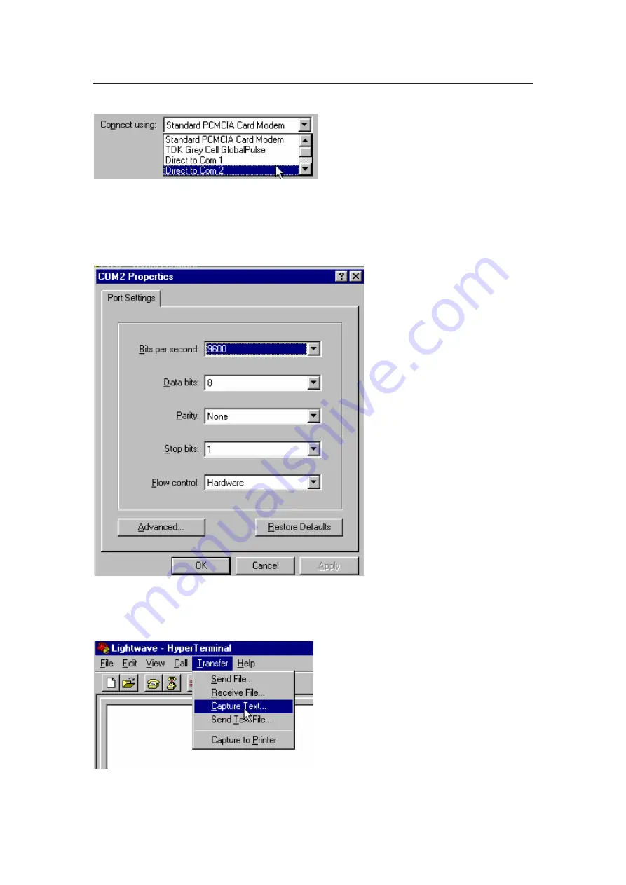
Select the correct COM port (which will be used to receive the Lightwave 
data) under “Connect Using” and then OK. 
 
Now set up the COM port: - 


Set the settings as above then press OK. 


To capture data, select Transfer - Capture Text. 


You will be asked for a file name - e.g. Lightwave.txt.  Then Press START. 

Summary of Contents for WPA Lightwave S2000

Page 1: ...truction Manual Lightwave S2000 UV Vis Diode Array Spectrophotometer Biochrom Ltd 22 Cambridge Science Park Milton Road Cambridge CB4 0FJ UK Tel 44 0 1223 423723 Fax 44 0 1223 420164 E mail enquires biochrom co uk Website www wpa co uk ...

Page 2: ...quipment for measurement control and laboratory use EN 61326 1998 Electrical equipment for measurement control and laboratory use EMC requirements Signed Dated 14th January 2003 David Parr Managing Director Biochrom Ltd Postal address Telephone Telefax Biochrom Ltd 44 1223 423723 44 1223 420164 22 Cambridge Science Park Milton Road e mail enquiries biochrom co uk website http www biochrom co uk Ca...

Page 3: ...ENSITY RATIO 15 10 4 1 Cell Density Measurement 15 10 4 2 Ratio Measurement 16 10 5 SCANNING 16 10 6 SELECT A METHOD TO RUN A METHOD SEE LATER IN MANUAL 17 10 7 TO PROGRAM A NEW METHOD OR RE PROGRAM AN EXISTING METHOD 18 10 8 RUN A METHOD 24 10 9 USING BI DIRECTIONAL COMMUNICATIONS 25 11 INSTRUMENT SET UP 25 11 1 COMMUNICATIONS 25 11 1 1 Printing 26 11 1 2 Connection to PC 28 11 2 SETTING UP THE L...

Page 4: ... We welcome any comments you may have regarding either the product or this manual Please contact Sales Co ordinator Tel 44 0 1223 423723 Fax 44 0 1223 420164 E mail enquires biochrom co uk 2 Conditions of Service The Lightwave is intended for use under cover at a temperature of between 5 and 40 C If dangerous or aggressive chemicals are used care should be taken to avoid spillage Normal precaution...

Page 5: ...aking a measurement both lamps Deuterium and Tungsten flash consecutively A self regulating circuit ensures flash to flash repeatability The data for each wavelength is recorded and stored in memory Stray light is minimised by positioning the diffraction grating after the cuvette compartment thereby eliminating the need for a light cover The use of a diode array detector allows simultaneous measur...

Page 6: ...ate Full spectrum measured simultaneously measurement time 5 sec Zero stability 0 003Abs hour after 20min warm up Noise 0 001Abs at 0A 500nm Modes of operation Scanning Ratio A260 A280 user adjustable Multi Wavelength Absorbance Transmission Concentration linear or curved calibration Kinetics Programmable up to 99 methods stored in battery backed memory Display 240 x 128 pixel dot matrix LCD Outpu...

Page 7: ...t hand corner of the display Similarly the Function keys on the left hand side of the display are only operational when a box appears Escape key takes the user back one step or aborts current operation Reference key zeros the instrument Test key makes a measurement across all wavelengths Arrow keys allow the user to navigate the screen Function keys 1 4 select function identified in box Symbols in...

Page 8: ...tte sizes in an accurate and repeatable manner Note It is important to align the square cuvettes to the far left hand side of the chamber The alignment of the cuvette is important to ensure re producible readings Results obtained using round cuvettes will be more variable due to unavoidable irregularities in the glass 10mm pathlength cuvettes should be placed here Tubes to be placed here 40 mm ...

Page 9: ...n as below Check that all tests are passed or contact our sales office authorised dealer Warm Up Time To allow the optical and electronic components to stabilise it is recommended to allow a minimum of 10 minutes for the unit to warm up For minimum drift leave the instrument for 45 minutes to 1 hour It is best practice to always take a reference measurement prior to making a TEST however the Light...

Page 10: ...of the fixed optical system or exposure to extreme temperatures Try leaving the unit on for a few minutes and then re start If the failure re occurs please consult your local dealer service agent or our service department Note The unit will continue to operate despite being out of wavelength calibration Failure of Diode Array On start up the unit checks that all pixels 512 are operating A failure ...

Page 11: ...l require a conversion factor to bring any one type of instrument in accord with another The Lightwave has a specific cell density function which has been developed to give readings in accordance with the average readings from a group of different spectrophotometers If used in single Absorbance mode rather than the cell density function in 10 4 1 readings will be considerably higher due to the nov...

Page 12: ...rial will normally be a low absorbing material often the solvent which is mostly water If the reference Absorbance is too high the instrument will display If this appears first check the type of cuvette being used Quartz for UV measurements If this is satisfactory consider an alternative reference material 9 2 Measurement at Low Levels 0 050A Due to the narrow beam size needed for use with small v...

Page 13: ...utton returns the user to the last screen displayed when the instrument was switched off This provides a short cut to the last test performed 10 2 Make a measurement 10 3 Single Multi λ This function key takes the user to a further menu screen allowing the option of single or multi wavelength measurements ...

Page 14: ...h settings can be changed in a similar manner to the single measurement mode and are memorised until re set Pressing function key 1 highlights the first wavelength setting others can be accessed by pressing the arrows Pressing function key 1 again allows the value to be changed using the arrows Pressing once more confirms the choice and moves to the next wavelength Once the user is satisfied with ...

Page 15: ... such samples Pressing REF will set the optical density OD to 0 000 on a blank sample The cell density measurements can then be made by pressing TEST The results are displayed in Optical Density Absorbance The attenuation of the primary light beam is measured and any stray or scattered light is rejected unlike other spectrophotometers with different optical set ups To compensate for this the absor...

Page 16: ... measurement mode and are memorised until re set Once set pressing REF or TEST will display the values in Absorbance on the screen and calculate the Ratio 10 5 Scanning The 512 pixel diode array captures readings from the complete wavelength range each time a measurement is made The scan displaying this information can be viewed on the graphics display Users may find it useful to look at the spect...

Page 17: ...fy the reading at a particular wavelength Note Due to the translation of pixel values onto the display screen the position of the cursor does not always correspond exactly to the maximum or minimum Absorbance To determine the maxima or minima with greatest precision please note the values given at the top of the display 10 6 Select a Method to run a method see later in manual Up to 99 methods can ...

Page 18: ...programmed into each method Name This can be an alpha numeric name of up to 13 characters including spaces λ Wavelength setting Cal Calibration Can be a curve or a straight line Display Absorbance Transmission or Concentration Units A choice of units that are available or none Factor This is only relevant for the straight line calibration will be displayed if the curve option is selected under Cal...

Page 19: ...t values Position the cursor against the next option and repeat the procedure to select the desired option Changing Wavelength Use up down arrows to change the wavelength Note The wavelength changes slowly at first and then more quickly dependent upon how long the arrow is pressed Calibration Line Curve To highlight Curve press then ACCEPT This will take you to a new screen see non linear calibrat...

Page 20: ...ct from a choice of units These will appear on the final result screen when the Method is run A choice of units can be made for concentration measurements If the chosen display is Absorbance or T the choice of units will be ignored Factor The Factor is only relevant to LINE calibrations and represents the multiplication factor to convert Absorbance into Concentration as per the Beer Lambert Law Co...

Page 21: ...omial fits the curve to the points exactly and since the program will not allow maxima or minima to prevent one reading having two possible values some combination of points will give rise to an error message Invalid Curve If this appears adjust the points slightly and re try It is sometimes worthwhile plotting the points out and trying to identify points that are difficult to fit on a smooth curv...

Page 22: ...hed press ACCEPT Once all the values are set press ALL OK The cursor will move to the first Absorbance measurement This can be set numerically following the same procedure as above Alternatively you may place the standard in the cuvette chamber and press TEST to write the value into the memory location If you make a mistake just re test the sample Once all the readings have been entered against th...

Page 23: ...is a minimum interval of 10 seconds End Time This increases in increments of the interval time The software can calculate automatically the change in Absorbance per minute A min using a least squares correction The correlation coefficient is displayed 1 000 is a perfect fit 0 000 is no fit along with A min and the concentration A min Factor To program the time place the cursor over the desired sel...

Page 24: ... start the run Kinetics Run During the kinetics run the screen will initially show the Start Time less time elapsed Once this reached zero the first measurement will be taken followed by more measurements at each selected interval until the End time is reached Each measurement is displayed on the screen in turn Once all the readings have been taken the calculated A min correlation coefficient and ...

Page 25: ... reference reading press Control R A series of R s will run across the bottom of the Lightwave screen and the PC will respond with REF DONE 4 To read a sample press Control T The Lightwave will respond with a row of T s running across the bottom of the Lightwave screen The data obtained will be transmitted to the PC in comma delimited ASCII Wavelength Value Abs A message of TEST DONE will be recei...

Page 26: ...arity None Stop Bits 1 Data Bits 8 If connecting to a PC at 38400 Baud the length of the cable should be no longer than 3m 11 1 1 Printing The unit is designed to print to a 40 column serial printer It is only possible to print to the WPA S2000P printer using 9600 Baud Printer Specifications Type Serial RS232 Protocol Text EPSON ESC POS format Protocol Graphics Sends graphics command 1B hex 01 hex...

Page 27: ... operation has been selected In the majority of cases the user will be asked to confirm the Sample Number or revise This will then appear on the printout Printing Format Format 1 On connection the following header will appear WPA S2000 Spectrophotometer Software Version 2 4 This format is used for basic Absorbance or Transmission measurements Format 2 The unit will essentially download the screen ...

Page 28: ...the speed of the base machine A slow 386 or 486 machine may miss data In such cases it is advisable to use a DOS based package such as Odyssey to collect data Before disconnecting or connecting the instrument turn the PC and Lightwave off to avoid damage to any part 11 2 Setting Up the Lightwave to a PC Link First connect the Lightwave and the PC using a suitable cable such as WPA part number S200...

Page 29: ...ram Manager Accessories Double Click on icon Hypertrm You will be asked for a suitable name e g Lightwave and an icon Once this is set up you can click on this icon and the settings will be loaded correctly You will then be asked to configure the phone number Ignore the first options and move the Connect using option ...

Page 30: ...t COM port which will be used to receive the Lightwave data under Connect Using and then OK Now set up the COM port Set the settings as above then press OK To capture data select Transfer Capture Text You will be asked for a file name e g Lightwave txt Then Press START ...

Page 31: ...er Select Transfer Capture Text Stop The file can then be imported into EXCEL TM directly using the Import Wizard within MS Excel TM The import wizard will detect the format automatically Importing Into Excel or similar spreadsheet program Open Excel and open the data file txt the following screen will be displayed Choose Delimited if not already chosen and press NEXT ...

Page 32: ...omma then NEXT Select General then FINISH The data will then appear as indicated in the excel spreadsheet To create a graph of the data if scan data use the graph facility in Excel You will need to re arrange the columns wavelength first Absorbance or T second ...

Page 33: ...llowing parameters COM1 COM2 Depending on which port you are using Usually the mouse is in COM1 and COM2 is available BAUD RATE 9600 PARITY None STOP BITS 1 DATA BITS 8 FLOW CONTROL Hardware with the parity check and carrier Detect boxes inactive WPA has set up an ExcelTM file sample xls to import the data and display Spectra This can be obtained from our sales office and e mailed to you or put on...

Page 34: ...arriage return value 2 wavelength 2 carriage return value 512 wavelength 512 carriage return checksum 1 Format 3 Dd mm yy hh min method no name sample number or ref elapsed time in mm ss value repeat for other values delta A min correlation coefficient display units Format 4 dd mm yy hh mm sample no or ref value units wavelength value units wavelength value units wavelength value units wavelength ...

Page 35: ...een and select Set Time Date Use the to change the setting or use the arrows to move between time and date settings Press Accept to confirm 11 4 Auto Print This function key takes the user to a second screen where the Auto print function can be toggled ON and OFF When the Auto print is ON the instrument automatically increments the Sample Number and outputs the data in the set mode PC or Printer e...

Page 36: ...e lamp replacement is a very infrequent event the lamps should last many thousands of hours The innovative method of operation requires a particular type of lamp The lamp alignment is also crucial to the correct operation and we cannot guarantee performance to the published specification if lamps other than those from WPA are used The part numbers for replacement lamps are as follows Tungsten Lamp...

Page 37: ...e cuvette compartment will not damage the instrument The grey cuvette holder can be pulled out to clear any spillage and to access the cuvette compartment Check that the cuvette tray has not accumulated any liquid or deposits from the storage of wet cuvettes Particular care should however be taken to avoid spillage when handling aggressive or organic liquids as these can damage the plastic mouldin...

Page 38: ...ns WPA instruments should not be used under such extreme conditions which would themselves constitute a danger to the operators The unit has been tested using a 2m RS232 cable connected however a longer lead may affect the level of EMC emission 14 Guarantee The Lightwave is guaranteed against faulty workmanship and components for two years In the unlikely event of service requirements other than L...

Page 39: ...del Number Instrument Serial Number Circle A if applicable otherwise circle and complete all parts of section B A This equipment including any accessories has not been in contact with blood or other body fluids respired gases or pathological samples It represents no hazard to health due to Physical Chemical Biological or Radioactive contamination of the unit B 1 This equipment been exposed interna...

Reviews: