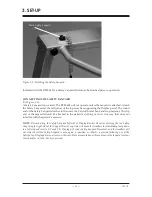
Figure 3.1. Attaching the Safety Lanyard.
Included with the RTM 600 is a Safety Lanyard that must be attached prior to operation.
connectInG the safety lanyard
(See Figure 3.1.)
A Safety Lanyard is provided. The RTM 600 will not operate unless the lanyard is attached. Attach
the Safety Lanyard at the left corner of the top cross bar supporting the Display panel. The round
end of the Safety Lanyard attaches to the unit via a Velcro® brand hook and loop fastener. The clip
end of the lanyard should be attached to the patient’s clothing or wrist in a way that does not
interfere with the patient’s exercise.
NOTE:
Disconnecting the Safety Lanyard (left side of Display/Control Panel) or pressing the red Safety
Stop (atop the right side of the Support Bar) at any time will cause the treadbelt to immediately ramp down
to a full stop and reset to 0.0 mph. The Display will read <Safety Lanyard Removed> and the treadbelt will
not restart until the Safety Lanyard is once again in position or <Start> is pressed following use of the
Safety Stop. Display data is not lost in either case. Data accumulation will resume once the lanyard is recon-
nected and/or <Start> has been pressed.
3. SET-UP
— 3-1 —
SET-UP
Attach Safety Lanyard
Summary of Contents for 950-284
Page 21: ......
Page 27: ......
Page 29: ......
Page 40: ...13 1 ASSEMBLY DRAWINGS AND SCHEMATICS 13 ASSEMBLY DRAWINGS AND SCHEMATICS...
Page 41: ...ASSEMBLY DRAWINGS AND SCHEMATICS 13 2 CONTENTS...
Page 42: ...13 3 ASSEMBLY DRAWINGS AND SCHEMATICS CONTENTS...
Page 43: ...ASSEMBLY DRAWINGS AND SCHEMATICS 13 4 CONTENTS...
Page 44: ...13 5 ASSEMBLY DRAWINGS AND SCHEMATICS CONTENTS...


