background image

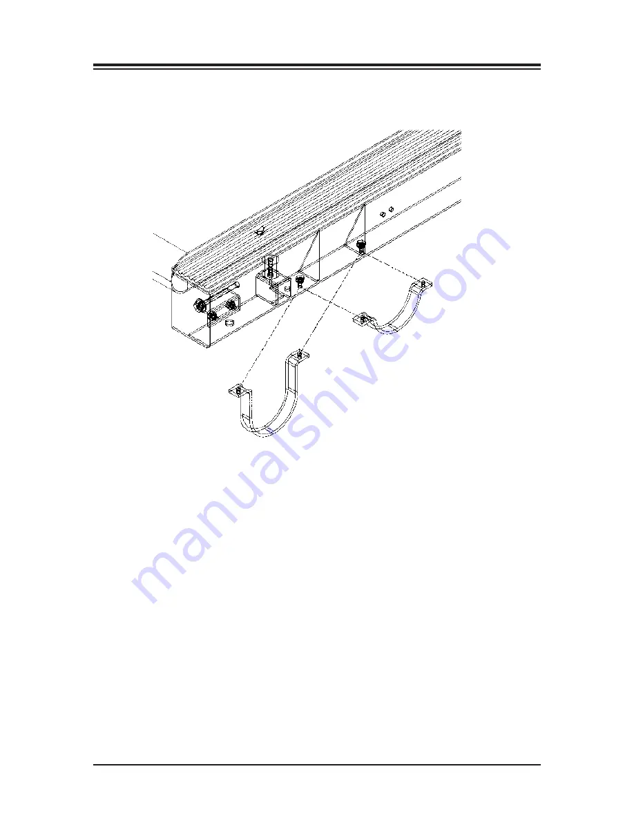
Figure 13.1. Installing the optional Elevation Rockers.

CONTENTS

OPTIONAL

— 13-2 —

Summary of Contents for 950-385

Page 1: ...85 950 386 950 387 950 395 950 396 950 397 950 398 BIODEX Biodex Medical Systems Inc 20 Ramsay Road Shirley New Y ork 11967 4704 Tel 800 224 6339 In NY and Int l call 631 924 9000 Fax 631 924 9338 Ema...

Page 2: ...IT TRAINER 2 98 131 0413 NOTE All or some of the following symbols cautions warnings and notes may apply to your Gait Trainer 2 and correspond to this operation manual Symbol Meaning Attention consult...

Page 3: ...EADMILL OPERATION 8 1 Quick Start Operation 8 1 Quick Start Track Numeric Display Parameters 8 2 Manual Treadmill Operation 8 3 Manual Mode Exercise Track and Numeric Display Parameters 8 4 9 TREADMIL...

Page 4: ...ower extremities in the desired patterns for gait thus reinforcing the prop er techniques early in the rehabilitation process As the patient progresses correct stride length is coupled to the correct...

Page 5: ...up onto the treadbelt 11 Instruct patients to use the handrails when first learning to walk on the Gait Trainer 2 1 Tous les patients doivent voir leur m decin responsable avant d entreprendre la s an...

Page 6: ...autre dans cette prise CONNECTING THE SAFETY LANYARD See Figure 3 1 A Safety Lanyard is provided The Gait Trainer 2 will not operate unless the lanyard is attached Attach the Safety Lanyard at the le...

Page 7: ...ures 3 2 3 4 Figure 3 2 Figure 3 3 Figure 3 4 The Biodex Gait Trainer 2 comes with a sturdy support bar installed Figure 3 2 Optional Standard Figure 3 3 and Geriatric Pediatric handrails Figure 3 4 a...

Page 8: ...nch lock washer and hex head bolt 3 Slide the handrail mounting bar into the bottom of the optional handrail so that the screw holes align 4 Attach the bottom of the handrail to the platform deck fram...

Page 9: ...TE It is recommended that the Biodex Unweighing System be used in conjunction with the Gait Trainer 2 to provide a safe environment for the patient and clinician and also to allow for proper patient p...

Page 10: ...to the Biofeedback Options Screen A brief explanation of each parameter and function on the Gait Training User Setup Information Screen follows NOTE For all screens Next advances to the next screen B...

Page 11: ...rameters and Functions Set Step Length Tolerance Range Touch Set Range and then use the pop up keypad to change the value Set Visual Biofeedback ON OFF Interval Time Touch ON OFF or Interval and enter...

Page 12: ...wn does not go in front of the opposite step the target box will not appear Footfalls Histogram Screen Parameters Touch Next at the Patient Setup Information screen to advance to the Footfalls Histogr...

Page 13: ...itoring is accomplished by having the subject hold onto both heart rate handgrips on the front handrail The heart rate value will be displayed at the top left of the screen when the handgrips are held...

Page 14: ...d in the Biodex Gait Trainer 2 id derived from the reference tables in Gait Analysis An Introduction 2nd Edition Michael W Whittle 1997 pgs 218 219 Cycle time in Whittle is seconds whereas the Gait Tr...

Page 15: ...is ON 2 Press the ON STANDBY key to activate the display panel and bring up the Opening Menu touch screen Touch Gait Trainer to advance to the User Set Up Information screen 3 Enter select the require...

Page 16: ...is pushed Total Distance This is the total distance traveled by the belt which is in essence the distance trav eled by the patient Average Walking Speed Normative values have been established and are...

Page 17: ...ng Exercise Summary Print Histogram Touch Histogram to print a histogram for this exercise session Save Results This option allows the user to save exercise results for later reporting or export as fo...

Page 18: ...Figures 7 2 and 7 3 Gait Trainer 2 printouts include a Biodex Gait Training Exercise Summary and Biodex Gait Training Exercise Histogram CONTENTS 7 3 EXERCISE RESULTS...

Page 19: ...as follows 1 Press the On Standby button on the display The Opening Menu should now be displayed 2 Touch Treadmill on the Opening Menu The Treadmill Opening Menu should now be displayed 3 Press Start...

Page 20: ...n one hour if exercise continues at the current rate This parameter is dependent upon a default weight of 150 pounds METs This value reflects the resting rate of Oxygen consumption with one MET equal...

Page 21: ...o the next screen Back returns the user to the previous screen 1 At the treadmill Opening Menu select Manual Start The Setup Options screen should now be displayed 2 At the Setup Options screen touch...

Page 22: ...distance in miles or kilometers that the patient is expected to complete in the exercise session Calories Toggle between Calories Total calories burned by the user during the exercise session Calorie...

Page 23: ...CONTENTS 8 5 TREADMILL OPERATION Figure 8 3 The Exercise Track display Figure 8 4 The Numeric display...

Page 24: ...een should now be displayed 3 At the Profile Setup Options screen enter the Time duration user s body weight and the maximum elevation for the exercise profile Touch Next to advance to the Profile Exe...

Page 25: ...PROFILES 9 2 Figure 9 1 The Select Profile screen allows the user to choose from five pre defined profiles Figure 9 2 At the Profile Setup Options screen users can enter values for time body weight an...

Page 26: ...the number 1 12 of the profile you would like to design Touch OK The Editing Profile screen should now be displayed with the number of the profile you have decided to design 4 Each exercise profile ca...

Page 27: ...CONTENTS TREADMILL PROFILES 9 4 Figure 9 4 At the Editing Profile screen clinicians enter values for speed elevation and time for each of up to ten stages for any profile...

Page 28: ...ss the Configuration Patient Management and System Maintenance not shown screens The Utilities Menu also displays technical information about the Gait Trainer 2 firmware version and cumulative hours o...

Page 29: ...electing low numbers along the bar will result in a darker screen while selecting high numbers makes the screen appear brighter Brightness levels range from 1 to 15 Tone Volume Touch any section of th...

Page 30: ...Figure 10 5 The Stored Patient Exercise screen To advance to the Patient Management screen from the Utilities Menu touch Patient Management Enter 781 at the Access ID Code prompt and touch OK The Pat...

Page 31: ...Histogram 2 Touch to highlight the patient file to print The Stored Patient Exercise screen should now be displayed showing the selected patient file 3 Touch Print Record to print out the patient file...

Page 32: ...Treadmill Diagnostic Display 2 Touch for the elevation until the elevation motor stops The reported elevation counts should be between 12 15 If not loosen the nut on the elevation pot and adjust the...

Page 33: ...mber of counts on the display for each placement of the weight 14 Place the 100 lb weight next to the right front side plate screw The weight should be on the belt and centered over the screw 15 Press...

Page 34: ...ain Gauge Board LED Codes D5 Should always be flashing This means the Microprocessor on the board is working D4 Indicates no weight is on the Treadmill when this LED is on D3 LED on auto calibrate is...

Page 35: ...rm water and mild detergent NOTE DO NOT use solutions containing ammonia Hardware computer components should be wiped clean as needed using a soft rag dampened with alcohol QUARTERLY MAINTENANCE Lubri...

Page 36: ...To re order lubricant kit use Biodex part 945 276 Each container provides 12 applications Figure 11 1 Squirt one half tube of lubricant between the belt and deck Reverse or Replace Treadbelt and Deck...

Page 37: ...efore testing treadbelt tension as described below turn the Gait Trainer OFF and unplug the system Moving parts on the Gait Trainer can cause serious injury Do not attempt to determine treadbelt tensi...

Page 38: ...e or during belt replacements To Adjust Fine Tracking Determine which side of the exact track groove the belt rib is riding on Mark treadbelt tracking position on deck Tighten the hex tensioning bolt...

Page 39: ...0 VDC 4mph 1 00 VDC 8mph 2 00 VDC If speed control signals are OK proceed to step 3 3 Check Amplifier Output The Output Terminals are located on top of amplifier and are designated m and m The Output...

Page 40: ...bolts that secure each rocker to the Gait Trainer frame 4 Replace the existing rockers with the new rockers replace the bolts and tighten until fully secure 5 With the aid of a second person rotate t...

Page 41: ...Figure 13 1 Installing the optional Elevation Rockers CONTENTS OPTIONAL 13 2...

Page 42: ...ical 1M of performance IEC 61000 4 4 Electrical Fast PWR Input leads 5 1 2 no degradation complied Transient Burst Kv pos neg 5KHz of performance Power Leads Rep Rate IEC 61000 4 6 Conducted 150 KHz t...

Page 43: ...Strap and contact handgrip Deck 1 thick 2 5 cm Reversible Teflon Impregnated High Density Composite Fiber Power 115 VAC 50 60 Hz 20 AMP dedicated line or 230 VAC 50 60 Hz 20 AMP dedicated line Include...

Page 44: ...R EFFECTS ON GAIT IN SUBJECTS WITH PARKINSON DISEASE Arch Phys Med Rehabil Vol 81 January 2000 Biodex 91 149 BROUWER B STROKE SURVIVORS BENEFIT FROM STRENGTH TRAINING Biomechanics Jan 2000 Biodex 91 1...

Page 45: ...ex 91 156 KUAN TS et al HEMIPLEGIC GAIT OF STROKE PATIENTS THE EFFECT OF USING A CANE Arch Phys Med Rehabil Vol 80 July 1999 Biodex 91 145 LAUFER Y et al THE EFFECT OF TREADMILL TRAINING ON THE AMBULA...

Page 46: ...5 USING THE BIODEX UNWEIGHING SYSTEM BALANCE SYSTEM AND GAIT TRAINER IN AN INTEGRATED REHABILITATION PROGRAM Abstract May 2001 Biodex 92 217 NIAM S et al BALANCE AND PHYSICAL IMPAIRMENTS AFTER STROKE...

Page 47: ...152 Biodex 91 151 TEIXEIRA SALMELA LF et al MUSCLE STRENGTHENING AND PHYSICAL CONDITIONING TO REDUCE IMPAIRMENT AND DISABILITY IN CHRONIC STROKE SURVIVORS Arch Phys Med Rehabil Vol 80 October 1999 Bi...

Page 48: ...OLFF M et al BEYOND STRIDE OTHER CONSIDERATIONS WHEN DECIPHERING GAIT OF PEOPLE WITH AMPUTATION Advance for Physical Therapists 28 32 March 9 1998 Biodex 91 140 CONTENTS 16 5 REFERENCES AND BIBLOGRAPH...

Page 49: ...17 ASSEMBLY DRAWINGS AND SCHEMATICS 17 1 ASSEMBLY DRAWINGS AND SCHEMATICS...

Page 50: ...98 131 0413 CONTENTS ASSEMBLY DRAWINGS AND SCHEMATICS 17 2...

Page 51: ...CONTENTS 17 3 ASSEMBLY DRAWINGS AND SCHEMATICS...

Page 52: ...CONTENTS ASSEMBLY DRAWINGS AND SCHEMATICS 17 4...

Page 53: ...CONTENTS 17 5 ASSEMBLY DRAWINGS AND SCHEMATICS...

Page 54: ...CONTENTS ASSEMBLY DRAWINGS AND SCHEMATICS 17 6...

Page 55: ...BIODEX Biodex Medical Systems Inc 20 Ramsay Road Shirley New Y ork 11967 4704 Tel 800 224 6339 In NY and Int l call 631 924 9000 Fax 631 924 9338 Email sales biodex com www biodex com...

Reviews: