SELECT
MODE
FAIL
ACCESS
POWER
◆
Packing List
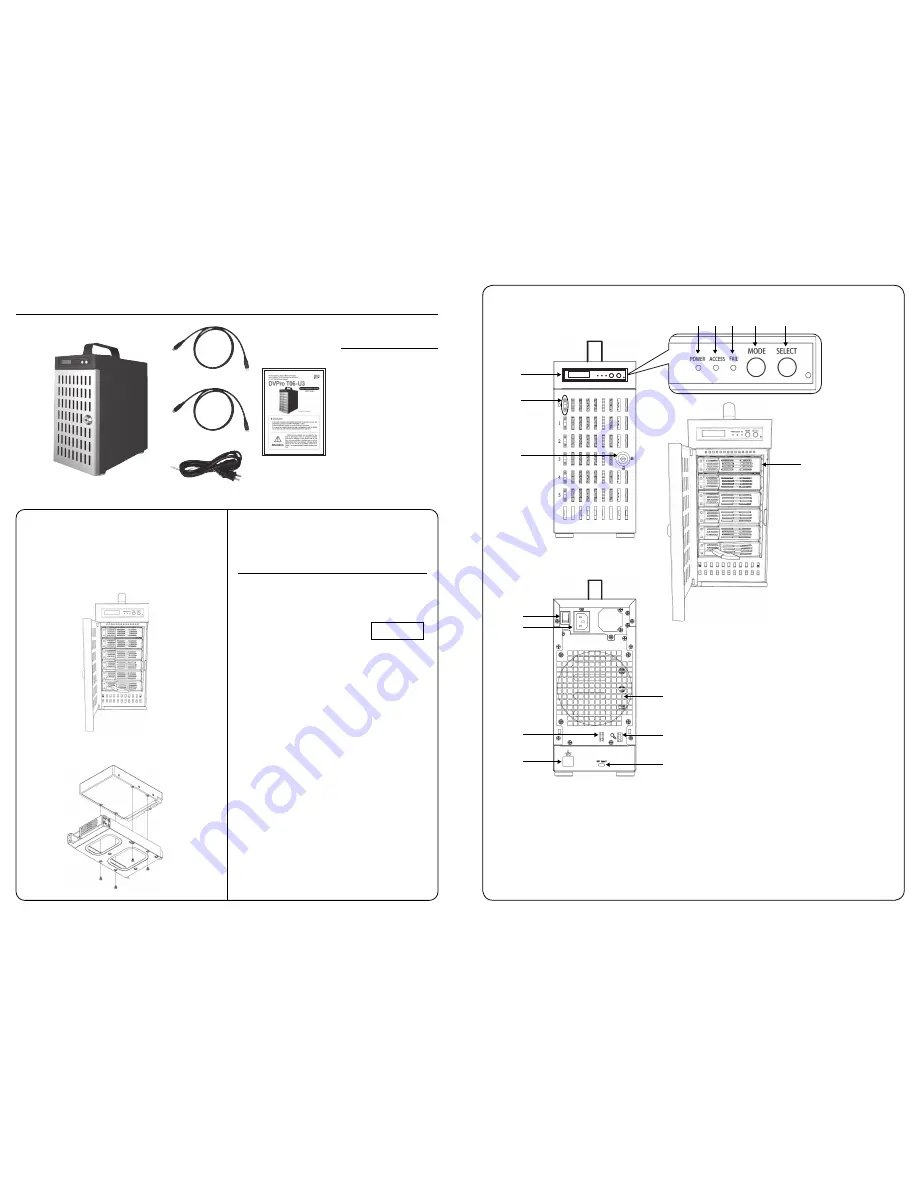
The box should contain the DVPro T06-U3 and below accessories:
DVPro T06-U3 Body
DVPro T06-U3
Quick Installation Guide
Power Cable
USB3.1 Type-C to C Cable
◇
Packing List
● DVPro T06-U3 Body
● Power Cable
● Screw Pack for Drives
● Quick Installation Guide
● 1M USB3.1 Type-C to C Cable
◆
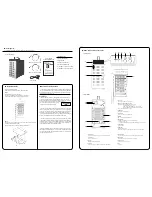
Name and Function of each part
<
Front View
>
<
Rear View
>
① Door Lock
Turn the key clockwise to open the door
② HDD On / Fail LED, HDD Access LED
Bule/Orange : Bule light indicates drive asserted,
Orange light indicates an error,
while “ RAID-x RECOVERING 0% ” shown on LCD,
the FAIL LED on means the HDD is under rebuilding
Green : Flash indicates disk accessing
③ POWER LED
Bule : Power ON LED indicator
④ ACCESS LED
Green : Controller Access LED indicator
⑤ FAIL LED
Red : A controller error LED indicator
⑥ MODE Button
1)Parameter Initialization ( Power on Initialization )
2)Configure parameters
3)Stop buzzer alarm ( Buzzer stopped immediately by pushing one time )
⑦ SELECT Button
Setup Parameter
⑧ LCD Display
Message display screen.
Show status of the system and parameters while doing configuration
To facilitate easy configuration of DVT06U3, a LCD/Keypad is designed on
the front panel for parameter setup. The default configuration and parameters
are designed to RAID6 mode. To avoid malfunction, parameters and configu-
ration could not be changed on use.
After then, one can change parameters value from Web GUI or LCD button
panel.
To quickly setup the unit, press “Mode” button to roll among different
parameters and “Select” button to choose different options. After change,
press “Mode” and “Select” at the same time to save modified parameters.
For details of each parameter and its meanings, please refer to User Manual
which can be downloaded from website: http://www.biosap.com.tw
The default setting might be varied for different configuration upon number
of pre-installed drives and capacity. Following parameters saved, please turn
off the power then press and hold the “Mode” button about 3 seconds while
turning on power to initialize the configured setting. New configuration or
parameters will be effective after initialization process.
Attention: Initialization process assumes data aligned to its RAID construc-
tion according to saved parameters. If the unit had corrupted data or failed
drive during last operation, the unit will still be enforced to “Normal” igonoring
possible error from its last state.
For Drive installation if needed,
Follow the below instruction to install or replace disk drive.
Step 1.
Use the attached key to open front door.
Turn the key clockwise to open it and get drive canisters out.
( Pull the tray handle from the hole as arrow sign shown )
Begin to use
There are two ways to configure the DVT06U3 setting either by Web GUI
or LCD and keypad operation. Most parameters cannot be changed
during normal operation to avoid possible corruption or malfunction. To start
with the parameter setting, both ‘Mode’ and ‘Select’ buttons
have to be pressed and hold at power on till the
LCD
showing [Array Parameter Setting!].
◆
Overview of Setup method
◆
Installation Guide
⑧
③ ④ ⑤
⑥
⑦
②
⑪
①
⑩
⑯
Step 2.
Put the drive on the canister with button screw holes toward it and drive
connector toward the opened space.
Get four screws from the screw bag and tightly screw them all.
⑫
⑭
⑬
⑮
⑨
⑨ Drive Module
Disk is count from channel 0 on top to channel 5 at bottom
⑩ Power Button
Turn On / Off the device
⑪ AC Input
AC Input ( 100V-220V support )
⑫ Cable Tie
Help to tie up Type-C cable by attached retractable ribbon
⑬ Key Chain Hook
Key chain can be hook here to avoid missing during transportation
⑭ Ethernet Port
RJ45 Fast Ethernet port for Web GUI management
⑮ USB3.1 Connector
USB3.1 host connector ( Type-C )
⑯ Fan
System Fan
USB3.1 Type-
A
to C Cable
● 1M USB3.1 Type-
A
to C Cable
$UUD\3DUDPHWHU
6HWWLQJ


