background image

Chapter 5 

Programmable Parameters

Evia HF / HF-T Technical Manual

PAGE 32

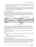
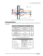
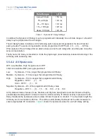
Rate Ranges

LOW

below 70 bpm

70—90 bpm

91—110 bpm

111—130 bpm

above 130 bpm

150 ms
140 ms
130 ms
120 ms
120 ms

Table  7:  Dynamic AV Delay Settings

In addition the Dynamic AV Delays may be programmed individually for each rate range or a fixed AV 

delay may be programmed for all ranges.
The AV Delay feature includes an AV shortening option (sensed compensation) for dual chamber 

pacing modes. The sense compensation can be programmed to OFF and –10 … (-5) … -120 ms. 

When selected, the AV delay after an atrial sense event is the AV delay after an atrial pace minus the 

sense compensation.
The Dynamic AV Delay is intended to mimic the physiologic, catecholamine-induced shortening of the 

AV Delay with increasing rate. 

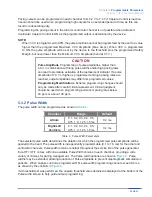
5.5.4.2   AV Hysteresis

OFF, Low, Medium, High, Negative and I-OPT
I-Opt not available if BiV pacing programmed
Low:  

Hysteresis - 70 ms longer than programmed AV Delay

Medium:  Hysteresis – 110 ms longer than programmed AV Delay
High:  

Hysteresis – 150 ms longer than programmed AV Delay 


Repetitive - OFF, 1 … (1) … 10 


Scan - OFF, 1 … (1) … 10

Negative: Hysteresis – 2/3 of the programmed AV Delay value 


Repetitive – OFF, 1 … (1) … 15 … (5) …100 … (10) …180

AV Hysteresis mode choices of Low, Medium and High are designed to promote intrinsic activity by 

periodically extending the AV interval to look for intrinsic activity. If intrinsic activity is present, the AV 

Delay maintains the hysteresis value to allow intrinsic R-waves to conduct.  The maximum length the 

AV Delay can be extended is 450 ms.  This will be automatically shortened as the rate increases to 

ensure appropriate AV conduction.  

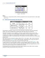
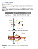
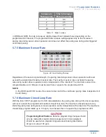
Table 8

 shows the hysteresis value for each AV Delay setting.

Summary of Contents for Evia HF

Page 1: ...Cardiac Rhythm Management Heart Failure Therapy Evia HF HF T Evia HF HF T Technical Manual...

Page 2: ...SF CAUTION Because of the numerous available 3 2 mm configurations e g the IS 1 and VS 1 standards lead pulse generator compatibility should be confirmed with the pulse generator and or lead manufactu...

Page 3: ...es 13 5 1 1 Motion Based Rate Adaptive Modes 13 5 1 2 CLS Modes 13 5 1 3 Non Rate Adaptive Modes 14 5 1 4 Mode Switching 14 5 1 5 Pacing Modes with Triggered Response 16 5 2 Rate Related Functions 17...

Page 4: ...ific Scenarios 44 5 8 1 2 1 Lock In Management 44 5 9 Atrial Upper Rate 45 5 10 Atrial Overdrive Pacing Overdrive Mode 45 5 11 Management of Specific Scenarios 46 5 11 1 PMT Management 46 5 11 2 PMT P...

Page 5: ...d Ventricular Rate Histogram 71 6 3 Arrhythmia Statistics 72 6 3 1 Atrial Burden 72 6 3 2 Time of occurrence 73 6 3 3 Mode Switching 73 6 3 4 Ventricular Arrhythmia 74 6 4 Sensor Statistics 75 6 4 1 S...

Page 6: ...iner 92 8 3 Pulse Generator Orientation 92 9 Lead Connection 93 9 1 Auto Initialization 94 10 Follow up Procedures 97 10 1 General Considerations 97 10 2 Real time IEGM Transmission 97 10 3 Threshold...

Page 7: ...Explant a Pulse Generator 113 13 Technical Data 115 13 1 Modes 115 13 2 Pulse and Control Parameters 115 13 2 1 Rate Adaptation 118 13 2 2 Atrial Capture Control ACC 118 13 2 3 Right Left Ventricular...

Page 8: ...Chapter Table of Contents Evia HF HF T Technical Manual PAGE vi...

Page 9: ...ar follow up visits allowing the physician to optimize the therapy process BIOTRONIK conducted the TRUST study to evaluate the safety and effectiveness of Home Monitoring With the TRUST study BIOTRONI...

Page 10: ...ed of two CRT Ps that are designed to handle a multitude of situations Evia HF Triple chamber rate adaptive unipolar bipolar pacing CRT P Evia HF T Triple chamber rate adaptive unipolar bipolar pacing...

Page 11: ...and Evia HF T Cardiac Resynchronization Therapy Pacemakers CRT Ps are indicated for patients who have moderate to severe heart failure NYHA Class III IV including left ventricular dysfunction EF 35 an...

Page 12: ...Chapter 2 Indications Evia HF HF T Technical Manual PAGE 4...

Page 13: ...nted cardioverter defibrillator ICD because it may cause unwanted delivery or inhibition of ICD therapy Single chamber atrial pacing is contraindicated for patients with impaired AV nodal conduction D...

Page 14: ...Chapter 3 Contraindications Evia HF HF T Technical Manual PAGE 6...

Page 15: ...er patients due to possible heating effects of the pulse generator and at the implant site If diathermy therapy must be used it should not be applied in the immediate vicinity of the pulse generator l...

Page 16: ...netic interference EMI to avoid damage to the device Temperature Stabilization Allow the device to reach room temperature before programming or implanting the device Temperature extremes may affect th...

Page 17: ...sion protocols should use non invasive programmed stimulation NIPS Unipolar Bipolar All Evia CRT P models can be used with either unipolar or bipolar IS 1 leads If the pacing or sensing function is to...

Page 18: ...hen programmed to triggered modes pacing rates up to the programmed upper limit may occur in the presence of either muscle or external interference Triggered Modes While the triggered modes DDT VVT an...

Page 19: ...ods shrouds etc are removed electrical tools anti theft devices of shopping centers and electrical appliances if not in proper condition or not correctly grounded and encased Patients should exercise...

Page 20: ...inimum separation of 12 inches 30 centimeters between the antenna and the implanted device Patients should hold the phone to the ear opposite the side of the implanted device Patients should not carry...

Page 21: ...ic rate increases when physical activity is detected by the motion sensor In demand modes DDDR DDIR DVIR VDDR VVIR AATR VVTR VDIR AAIR it is possible that the atrial and or ventricular refractory peri...

Page 22: ...xclude their recognition altogether However this phenomenon will not limit the functionality of the mode switch Motion based rate adaptive pacing will take over if the CLS pacing algorithm switches in...

Page 23: ...With Biventricular pacing programmed ON pacing during Mode Switch will be Biventricular as well Onset Criterion The mode switch onset criterion uses an X of 8 rolling counter with a default X value o...

Page 24: ...may be associated with an inappropriately tracked atrial tachycardia 2 1 Lock in Protection behavior is more likely to occur if the far field protection parameter is programmed too long greater than 1...

Page 25: ...temporary setting in situations where maintaining the programming head in place would be impossible or impractical i e during exercise testing or extended Holter monitoring or as a short term solution...

Page 26: ...n active as long as the intrinsic activity remains above the programmed hysteresis rate When the intrinsic rate falls to the hysteresis rate the device will deliver one paced event at the hysteresis r...

Page 27: ...rate Paced event 1 7 8 1 7 9 1 8 0 Scan Hysteresis programmed to 5 cycles 1 2 3 4 Hysteresis rate Basic rate Paced event 1 7 8 1 7 9 1 8 0 Scan Hysteresis programmed to 5 cycles Sensed event Figure 4...

Page 28: ...count has been met the device uses the standard rate hysteresis Repetitive hysteresis has been incorporated to promote spontaneous cardiac rhythm and may reduce pulse generator energy consumption NOT...

Page 29: ...s Night rate is clock based Night rate start and stops times are programmable in 10 minute increments The blue conflicts show permanent programming conflicts when ventricular capture control VCC is pr...

Page 30: ...pulse generator calculates the Fading Rate which is a four beat average of the intrinsic rate reduced by 10 ppm When the intrinsic rate drops considerably below the Fading Rate the pacing rate begins...

Page 31: ...rogrammed values Programming Modifications Extreme programming changes should only be made after careful clinical assessment Clinical judgment should be used when programming permanent pacing rates be...

Page 32: ...ge to a lower sensitivity higher value may resolve the difficulty In dual chamber sensing modes the sensitivity values for the atrial and ventricular channels are independently programmable With unipo...

Page 33: ...ion of the next event The sensitivity can never go below the minimum threshold shown below in the sensed event summary Atrial and ventricular ASC function for sensed events are the same except that th...

Page 34: ...e 200 ms 250 ms 2 x 125 ms 2 0 mV Minimum Threshold 2 0 mV Detection Hold off Period DHP 2x Step Duration Sensitivity Threshold from the previous event Sensitivity Threshold of the current event Event...

Page 35: ...omatic Sensitivity Control for Atrial Unipolar Paced Events Ventricular Pacing Overview Table 5 shows a ventricular pacing overview and applies to bradycardia programming and Mode Switch programming P...

Page 36: ...equal to the upper tracking Interval in ms when programmed to Auto This feature prevents the delivery of a LV paced event whenever a LV sensed event occurs first It is also designed to prevent pacing...

Page 37: ...Short Pacing Intervals Use of short pacing intervals high pacing rates with long atrial and or ventricular refractory periods may result in intermittent asynchronous pacing and therefore may be contra...

Page 38: ...d by the algorithm both the PVARP and PVARP after PVC is reduced by 50 ms every 7 days but no less than the minimum value of 175 ms 5 5 3 2 Right Ventricular Refractory Period 200 25 500 ms The right...

Page 39: ...r decrease the AV Delay setting for a particular rate bin 5 5 4 1 Dynamic AV Delay The AV delay defines the interval between an atrial paced or sensed event and the ventricular pacing pulse If the pul...

Page 40: ...of the AV Delay with increasing rate 5 5 4 2 AV Hysteresis OFF Low Medium High Negative and I OPT I Opt not available if BiV pacing programmed Low Hysteresis 70 ms longer than programmed AV Delay Med...

Page 41: ...95 ms 335 ms 370 ms 250 ms 320 ms 360 ms 400 ms 300 ms 370 ms 410 ms 450 ms 350 ms 420 ms 450 ms 450 ms Table 8 AV Hysteresis Settings 5 5 4 3 AV Repetitive Hysteresis With AV Repetitive Hysteresis th...

Page 42: ...ue corresponds to the programmed AV delay multiplied by approximately 2 3 limited to a minimum of 15 ms The normal AV delay resumes after the programmed number of consecutive ventricular paced events...

Page 43: ...nd Repetitive Hysteresis values are set to 5 and function as previously described Figure 19 I Opt Subsequent to switching I Opt on the range of values is pre configured as follows Function I Opt Stand...

Page 44: ...ed statistical information about the As Vs and Ap Vs interval distribution within the user interface for programming the AV delay settings see Figure 20 The recorded As Vs and Ap Vs interval distribut...

Page 45: ...ensed and paced ventricular events The Far Field Protection in the atrial channel feature affects both sensed and paced events originating from the ventricle and sensed on the atrial channel The progr...

Page 46: ...a block mode emerges or until Mode Switching occurs In a 2 1 block zone the ventricular pacing rate is half the intrinsic atrial rate The 2 1 ratio between the atrial and ventricular rate is maintain...

Page 47: ...Bipolar sensing offers an improved signal to noise ratio due to the decreased susceptibility to interference signals like skeletal myopotentials or EMI and therefore permits programming of higher sens...

Page 48: ...le for tailoring the motion based rate adaptation to the individual patient except for the maximum closed loop rate which is relevant to CLS Table 10 shows a summary of the parameters associated with...

Page 49: ...in parameter adjusted automatically Figure 26 Automatic Gain Programming When the Automatic Sensor Gain is activated the pulse generator samples the sensor indicated rate The sensor gain will be incre...

Page 50: ...lated to exertion If the pacing rate at rest is unstable or tends to stay above the lower rate without activity the sensor threshold should be increased The sensor threshold should be reduced if a suf...

Page 51: ...rate during sensor driven operation and is independent of the rate limit The maximum sensor rate programmable up to 180 ppm must be less than or equal to the programmed UTR NOTE In the DDIR and DVIR m...

Page 52: ...s an atrial rate that is half of the actual rate the pulse generator does not Mode Switch during an atrial tachycardia as programmed With 2 1 Lock In Management the tachycardia is detected and confirm...

Page 53: ...e are high sensor rates the atrial pacing is shifted NOTE Right atrial pacing does not occur when mode switching is activated and when the atrial upper rate is activated in DDI mode at the end of the...

Page 54: ...ety rate the preventive overdrive pacing is reactivated activation deactivation only in a 12 hour rhythm If the function is deactivated for a third time because the average safety rate has been exceed...

Page 55: ...hm consists of suspicion confirmation and termination components and is described as follows Suspicion A PMT is suspected when the following criteria are met The heart rate is greater than 100 bpm 8 s...

Page 56: ...and responds to any loss of capture with a safety back up pulse During the clinical evaluation of the Ventricular Capture Control algorithm it was demonstrated that use of Ventricular Capture Control...

Page 57: ...V 3 6 V 4 2 V and 4 8 V default 3 0 V This is the starting voltage when Capture Control ON or ATM is looking to determine the current threshold This value should only be changed to a higher value if...

Page 58: ...of the VCC feature that periodically measures the ventricular pacing threshold ATM can only occur after a successful CV Evoked Response The intracardiac signal measured during electrical activation of...

Page 59: ...SA is performed in two separate phases In both phases the AV delay is shortened to 50 ms after a paced atrial event and to 15 ms after a sensed atrial event to ensure ventricular pacing First five ven...

Page 60: ...and the programmed safety margin If two non captures are detected when the voltage decrements are greater than 0 1 V the pacing amplitude is set to the previous amplitude and then the amplitude decre...

Page 61: ...ur Non capture during SA non capture occurs twice in the second through fifth cycles of the SA at the maximum voltage amplitude setting High polarization artifact during SA the polarization artifact m...

Page 62: ...evice will continuously monitor the cardiac signal following the pacing pulse to verify that a depolarization occurred as a result of the pulse Upon detection of non capture the device will issue a ba...

Page 63: ...ventricle 2 Threshold search The threshold is determined by decreasing the amplitude stepwise at a programmed pulse duration until loss of capture occurs Loss of capture for one test amplitude is decl...

Page 64: ...output to which the device can be automatically programmed regardless of the measured threshold The Minimum amplitude can never be programmed higher than the Threshold test start value This restrictio...

Page 65: ...the device starts in the Vp DDD R state and looks for intrinsic conduction by starting a Vs searching Following any suspension e g Mode Switch the Vp Suppression feature will resume in Vp DDD R state...

Page 66: ...is limited to 15 attempts per hour When the limit is reached the Vp Suppression feature is suspended until midnight 12 00 AM and will then resume the Continuity test starting with the 30 second searc...

Page 67: ...with high CLS response Mode DDD VVI CLS DDD CLS DDD CLS DDD CLS Basic Rate 50 70 50 50 50 Night Rate OFF Rate Hysteresis ppm 10 Rate Hysteresis Rep Scan Cycles 5 Max Sensor Rate 130 120 90 120 120 CL...

Page 68: ...gin 1 0 1 0 1 0 1 0 1 0 Search type Time of Day Time of Day Time of Day Time of Day Time of Day Time of day 2 00 2 00 2 00 2 00 2 00 PMT ON ON ON ON High Atrial Rate Mode Switch Mode Switch Mode Switc...

Page 69: ...lant and the patient device must be 6 inches 15 cm 5 18 2 Patient Device The patient device is designed for use in or away from the home and is comprised of the mobile unit and the associated charging...

Page 70: ...dio Report from the implant can be triggered as follows Trend report the time period daily initiates the report Event report the pulse generator detects certain events which initiate a report 5 18 4 1...

Page 71: ...by the Home Monitoring system when activated In addition to the medical data the serial number of the implant is also transmitted Device Status Home Monitoring Settings Containing device and message...

Page 72: ...ttings e g ON OFF transmission time daily IEGM transmissions ON OFF periodic IEGM ongoing atrial episode statistics holter Miscellaneous other information 5 18 5 1 IEGM Online HDs The Evia HF T provid...

Page 73: ...te Trend 24 hours Rate Trend 240 days Rate Histograms Atrial Arrhythmia Atrial Burden Time of Occurrence Mode Switching Sensor Sensor Histogram Activity Report Sensing P R wave Trends Far Field Histog...

Page 74: ...ry of what each event means Event Counters In the Event counters shown in Figure 35 the legend is as follows As refers to atrial sensed events As PVARP refers to atrial events occurring during the PVA...

Page 75: ...s falling into the PVARP timer and outside the Discrimination after As window Likely examples of these types of events include non conducted PAC events or events occurring during Mode Switch Ars event...

Page 76: ...LV RV sequences where RVs occurs without an LVp If the RVs triggering feature is turned OFF this counter will display 0 PVC triggered LVp is the percentage of all LV RV sequences where an LVp was trig...

Page 77: ...cording period The graph is rolling keeping only the most current data Ars FFP and Vrs events are not counted in the Rate Trend Key Points The 24 hour rate trend provides a time based profile of atria...

Page 78: ...ar 24 hour recording period The percentage pacing is the percentage derived during that particular 24 hour recording period As FFP and Vrs events are not included in Rate Trend 240 days Key Points The...

Page 79: ...resents the programmed maximum sensor rate value regardless of whether the sensor is active Key Points The Rate Histogram displays the percentage of paced and sensed events in each rate bin listed alo...

Page 80: ...he 36 48 event above the programmed high atrial rate criteria is met Recording is stopped when the termination count of 24 36 is met Mode Switch events that do not meet the HAR criteria of 36 48 will...

Page 81: ...hmia episodes began and is broken into three hour time blocks Knowing the time of day when atrial tachyarrhythmias begin may help determine whether a particular event will precipitate the tachyarrhyth...

Page 82: ...RT P counts each type of PVC sequence Each sequence is counted in the sum total below the bar graph in Figure 43 The Sum value is the total number of sequences that have occurred Each sequence is also...

Page 83: ...liminates the possibility of PVC events being miscounted as a result of atrial undersensing 6 4 Sensor Statistics 6 4 1 Sensor Histogram This function records how often the sensor rate is within certa...

Page 84: ...ted by intrinsic events NOTE When Event Counters exceed 8 digits they are presented in exponential form Heart Rate and Sensor Rate Histograms will switch to exponential form when the Counters exceed 6...

Page 85: ...ics 6 5 1 Lead Impedance Trends with Lead Check Evia CRT Ps can perform lead impedance measurements for the atrial and right left ventricular leads These measurements are stored in memory for use in l...

Page 86: ...histogram The percentage and total number of 2 second intervals occurring within an amplitude class is displayed Recording stops when ACC or RVCC LVCC are disabled between follow ups or if the memory...

Page 87: ...HF HF T will also count each output during the capture control test 6 5 4 Capture Control Status The Capture Control Status displays the status threshold last value including time and date current pac...

Page 88: ...herefore the most recent data are available for review Figure 50 P R Wave Trend The P R wave trend graph shown in Figure 50 shows the sensing results for P and R wave measurements The graph collects d...

Page 89: ...ents outside the programmed far field protection interval will be shown in the white portion of the graph 6 6 3 Ap Vs interval distribution curve This graph provides information related to the amount...

Page 90: ...amount of Vs response to atrial sensed events The information is divided into 5 rate bins and provides the minimum mean and maximum Ap Vs intervals for each rate bin The data is also displayed on a gr...

Page 91: ...nd has a value range of 0 to 180 bpm The daily value is stored for a period of 240 days After 240 days new daily values shall replace the oldest daily values The programmer presents the daily bpm valu...

Page 92: ...threshold The cumulative daily time when the sensor is active is stored in the device for a period of 240 days After 240 days new daily values replace the oldest daily values 6 7 5 Thoracic Impedance...

Page 93: ...hour Measurements averaged to a single data point Thoracic impedance should NOT be used as a stand alone parameter to determine CHF Variables such as COPD and hypovolemia may affect measurement values...

Page 94: ...wenty separate IEGM recordings that each include approximately 10 seconds per event Upon interrogation of the Evia HF T pulse generator containing stored IEGMs a list of the stored IEGMs with date and...

Page 95: ...hronous pacing the AV interval is reduced to 100 ms 7 2 2 Asynchronous Magnet Effect When programmed to asynchronous operation magnet application results in asynchronous pacing The pulse generator pac...

Page 96: ...tient should be activated as a temporary program only When interrogating the pulse generator the permanent program will always be displayed and documented even though a temporary program was activated...

Page 97: ...puterized systems are subject to EMI or noise In the presence of such interference telemetry communication may be interrupted and prevent programming A sensed event occurring during the interference i...

Page 98: ...Chapter 7 Product Storage and Handling Evia HF HF T Technical Manual PAGE 90...

Page 99: ...age temperature Recommended storage temperature range is 10 to 45 C 14 113 F Exposure to temperatures outside this range may result in pulse generator malfunction Handling Do not drop If an unpackaged...

Page 100: ...moved using standard aseptic technique and placed on the sterile field Peel off the sealing paper of the outer container as indicated by the arrow Take out the inner sterile container by the gripping...

Page 101: ...For questions regarding lead generator compatibility consult your BIOTRONIK representative In case of pulse generator replacement make sure that the existing lead connector and lead are not damaged C...

Page 102: ...ing System Be sure to properly insert the torque wrench into the perforation at an angle perpendicular to the connector receptacle Failure to do so may result in damage to the plug and its self sealin...

Page 103: ...this phase confirm the lead detection and lead polarity The impedance measurements need to fall within the range of 100 to 2500 Ohms A lead impedance measurement outside this range restarts the confir...

Page 104: ...Chapter 9 Lead Connection Evia HF HF T Technical Manual PAGE 96...

Page 105: ...ter implantation by pressing the Transmit Program button CAUTION Programming Modifications Extreme programming changes should only be made after careful clinical assessment Clinical judgment should be...

Page 106: ...automatically in the DDD VDD and VVI modes and will be performed the same way the VCC test is performed Figure 57 Threshold Test Choices The atrial test can be performed in the DDD or AAI modes as wel...

Page 107: ...while the test is ongoing If a value is changed the device will automatically stop the ongoing test and then restart the test with the new value s Figure 58 The Pacing Threshold Test Screens Demonstr...

Page 108: ...printer speed Otherwise an annotated version of the test can be printed after the test by selecting the Print button which is found in the lower left corner of the screen To determine the threshold th...

Page 109: ...played on the programmer screen when the test is complete An IEGM strip can be printed during the test with Report set to a user defined printer speed 10 4 2 Intrinsic Rhythm test The sensing test can...

Page 110: ...th the Sensing test These are all temporary values activated during the test 10 4 4 Sensing test parameters 10 4 4 1 Basic Rate 30 1 90 2 122 3 140 5 200 ppm Default value of 30 ppm The Evia CRT P wil...

Page 111: ...ected sensitivity level should be checked for possible interference from skeletal myopotentials If oversensing is observed the programming of a lower sensitivity higher value or bipolar sensing functi...

Page 112: ...asurement is initiated from the Retrograde conduction tab During the test the pacemaker operates in VDI mode at a programmable rate that must exceed the heart s intrinsic rate The V A interval is meas...

Page 113: ...ed via the main Follow up screen The last follow up icon is in the upper right hand corner of the follow up screen Figure 66 Follow up History Page 10 6 Atrial Non Invasive Programmed Stimulation NIPS...

Page 114: ...rogram Burst Stimulation may be stepped up or down from the nominal value to user defined high or low limits as long as the selection is touched on the touch screen When the Step Up or Step Down key i...

Page 115: ...essions When the battery voltage has reached the Elective Replacement Indicator point ERI the NIPS feature is no longer available Atrial pacing support is available to pacemaker dependent patients dur...

Page 116: ...ince the time period immediately preceding the follow up may be evaluated When in doubt about the suitability of particular sensor settings for a certain patient the sensor rate forecast can be utiliz...

Page 117: ...to cause a rate increase This parameter is meant to assure a stable pacing rate at rest and to prevent rate increases at signal levels not consistent with physical exertion The sensor gain should be...

Page 118: ...Chapter 10 Elective Replacement Indication ERI Evia HF HF T Technical Manual PAGE 110...

Page 119: ...fies the end of the elective replacement indication period Table 21 Service Cycle Definitions The pulse generator indicates the need for replacement by a defined decrease in the programmed rate withou...

Page 120: ...imated time to ERI in months and years that is updated each time the device is reprogrammed This estimation allows the physician to understand the longevity effects of modifying programmed parameters...

Page 121: ...cations related to other portions of the pacing system i e lead patient may also result in pulse generator explant Table 25 summarizes some of the more common reasons for pulse generator explant Sourc...

Page 122: ...ibrillation Patient Threshold Elevation Loss of capture and or sensing Normal medical complication Infection Body rejection phenomena Fluid accumulation migration erosion Misc Unipolar pacing systems...

Page 123: ...ead impedance of 500 ohms 13 2 Pulse and Control Parameters Basic rate 30 1 60 1 88 2 122 3 140 5 200 ppm Night rate Off 30 1 60 1 88 2 122 3 140 5 200 ppm Rate Hysteresis Off 5 5 90 bpm Repetitive Sc...

Page 124: ...PT AV Scan Repetitive Hysteresis Off 1 1 10 Negative AV Hysteresis Off 1 1 10 5 100 10 180 AV safety delay 100 ms Sense Compensation Off 10 5 45 5 120 ms Far Field after Vs 100 10 220 ms Far Field aft...

Page 125: ...0 1 3 0 0 1 6 0 0 5 7 5 V Pulse width A 0 1 0 2 0 3 0 4 0 5 0 75 1 0 1 25 1 5 ms RV 0 1 0 2 0 3 0 4 0 5 0 75 1 0 1 25 1 5 ms LV 0 1 0 2 0 3 0 4 0 5 0 75 1 0 1 25 1 5 ms Sensitivity A AUTO 0 1 0 1 1 5...

Page 126: ...threshold very low low medium high very high Rate increase 1 1 10 ppm cycle Maximum sensor rate 80 5 180 ppm Rate decrease 0 1 0 2 0 5 1 0 ppm cycle Automatic Sensor Gain Off On 13 2 2 Atrial Capture...

Page 127: ...1 2 V LV 1 0 or 1 2 V Search Scheduling Interval Time of Day Interval 0 1 0 3 1 3 6 12 24 hours Time of Day 00 00 23 50 in 10 minute increments nominal 02 00 13 2 4 Home Monitoring Parameters Home Mon...

Page 128: ...er head 24 hour Trend Heart Rate Histogram Sensor Rate Histogram Sensor Test Trend with complete Rate Forecast Automatic Sensor Gain with Trend Monitor PVC Analysis Retrograde Conduction Test Mode Swi...

Page 129: ...receptacle Epoxy resin Sealing Plugs Silicone Rubber 13 5 Electrical Data Battery NOTE At 37 C with pacing impedance of 500 Ohms Parameter Evia HF HF T Pace Unipolar bipolarr Pulse form Biphasic asymm...

Page 130: ...Chapter 13 Order Information Evia HF HF T Technical Manual PAGE 122...

Page 131: ...erference that may be caused by such stations including interference that may cause undesired operation This transmitter shall be used only in accordance with the FCC Rules governing the Medical Devic...

Page 132: ...Chapter 14 Order Information Evia HF HF T Technical Manual PAGE 124...

Page 133: ...a broad range of rates such as active or young patients with an adequate increase in atrial rate and or significant hemodynamic indication and or previous occurrence of pacemaker syndrome or of a red...

Page 134: ...ry for hemodynamic optimization and or a pacemaker syndrome has already occurred or is expected The VDD mode is conditionally indicated for patients with normal sinus rhythms and normal AV conduction...

Page 135: ...that adequate AV conduction has been established by an appropriate diagnostic examination The AAI mode is contraindicated for previously established AV conduction delay or AV block or if diminishing A...

Page 136: ...PAGE 128 Appendix A Evia HF HF T Technical Manual...

Page 137: ...effect on patient since there is no impact on the permanent or temporary device therapy Interrogation from implant list updates the parameters If Auto PVARP is set to OFF after it was set to ON at in...

Page 138: ...HF HF T Technical Manual BIOTRONIK Inc 6024 Jean Road Lake Oswego OR 97035 5369 800 547 0394 24 hour 800 291 0470 fax www biotronik com M4142 B 09 16 2016 BIOTRONIK Inc All rights reserved MN019TEr1 9...

Reviews: