background image

27

Appendix

Disclaimer

Conditions of use and 

requirements

Implantable BIOTRONIK leads (called "leads" in the following) are sophisticated, 
precision mechanical medical products. 

They should be as thin and flexible as possible.

After implantation, they are subjected to great stress due to the mobilization of the 
immune defense of the human organism.

Although they are designed to function reliably for many years under the given 
conditions, their resilience and durability are limited.

Risks and possible 

complications

Problems or failures that occur during or after lead implantation can have many 
causes. 

For example: 

Medical complications

Foreign body rejection phenomena

Fibrosis

Lead dislodgement

Erosion

Migration through body tissue

Insulation defect

Risk of damage

Despite meticulous care in development, material selection, production, and final 
inspection prior to delivery, leads can be easily damaged in the event of improper 
handling or use.

Limitation of liability

BIOTRONIK does not guarantee that the following events will not occur: 

Lead malfunctions or failures

Defense reactions of the body against lead implantation

Medical complications (including myocardial perforation) during lead 
implantation or as a consequence of implanting the lead

The same applies to implantation and lead accessories by BIOTRONIK.

Burden of proof for defective 

goods

The state of the product at the time of sale is critical for any product returns.

No liability is assumed for any defects not immediately detected upon receipt of the 
goods.

Responsibility for 

complications and 

consequential damage

The buyer/user bears the entire risk associated with the use of the lead.

BIOTRONIK shall not be liable for any loss, damage, or injury of any nature, whether 
direct, indirect, or consequential, that may occur in connection with the leads and 
accessories or their use.

BIOTRONIK shall not reimburse the customer or a third party for any costs incurred 
in connection with the use, malfunction, or failure of any lead or accessory, 
including physician's fees, hospital expenses, medication costs, subsidiary costs, 
and costs for consequential damages.

Final clause

No one is authorized to hold BIOTRONIK liable for any statement or warranty 
deviating from the above.

Summary of Contents for ProMRI Protego DF-1 S

Page 1: ...les biotronik com www biotronik com Protego DF 1 S ProMRI Tripolar ICD lead with active fixation Technical Manual 414086 Revision E 2015 05 28 BIOTRONIK SE Co KG All rights reserved Specifications sub...

Page 2: ...lectrical and Electromagnetic Safety 10 Handling and Implantation 11 Implantation Basic Instructions and Safety Measures 11 Information on the Steroid Collar 12 Opening the Package 13 Checking the Fun...

Page 3: ...risks and possible complications Note Keep this technical manual for later use This technical manual This technical manual is either included in hard copy form in the product packaging or can be down...

Page 4: ...improve the lead s gliding properties Details Technical Data p 24 ff Electrical properties The fixation screw is electrically active and forms the distal pole tip electrode of the lead Sensing and pa...

Page 5: ...tines is not possible Contraindications Implantation of this lead is contraindicated in the following cases Patients with mechanical tricuspid valve prostheses or severe tricuspid valve diseases Patie...

Page 6: ...bolisms and damage to the device Resterilization and reuse are prohibited CAUTION Improper storage If the specified time period and temperature range for storage are exceeded then the documented prope...

Page 7: ...nctions of the device system which consists of pacemaker or ICD and leads Incorrect lead implantation Lead dislodgement Lead fracture Insulation defect Battery depletion or component failure of the ac...

Page 8: ...ducts are actually certified MR conditional in your country or region Procedure Type of danger Diathermy Tissue damage due to excessive heating of the lead Induction of ventricular fibrillation Magnet...

Page 9: ...s Thermal tissue damage in severe cases The patient should be properly informed and instructed on behaviors to avoid situations with especially risky electromagnetic effects Perform a follow up for cl...

Page 10: ...electromagnetic energy as an antenna would and cause electrical voltages at the lead tip and connector This can induce ventricular fibrillation in some cases as well as damage or otherwise affect the...

Page 11: ...of the stylet in the lead and inhibit or block the screw mechanism Ensure that no blood reaches the interior of the lead on or with the stylet As far as possible prevent blood from entering the lead...

Page 12: ...ate The intended effect is the reduction of the inflammatory processes after implantation and the inflammation related post operative threshold increase lead maturation behavior Long term performance...

Page 13: ...hin the other and sterilized with ethylene oxide As a result the inner blister is also sterile on the outside You can remove the inner blister by using a standard aseptic technique and place it in the...

Page 14: ...chanism are not suitable for implantation Do not implant the lead if it fails the function test Instead use a replacement lead that has passed the same test Step Action 1 Remove the stylet guide from...

Page 15: ...sing loss due to excessive mechanical stress of the lead Make sure the lead does not become pinched between the clavicle and the first rib after implantation After having established the access to the...

Page 16: ...crew is retracted Thus the position of the lead tip can be assessed prior to fixation using electrocardiac measurements without injuring the tissue Fixating the lead tip Proceed as follows to fixate t...

Page 17: ...ully when fixating the lead tip Consider the following two aspects when elongating between the distal and proximal fixations of the lead The patient s own movement and heart contractions should not ex...

Page 18: ...asurements pacing will be temporarily interrupted Connecting the leads temporarily For a qualitative evaluation of the lead position it is necessary to measure pacing thresholds intracardiac potential...

Page 19: ...the respective testing and measuring devices for further details on performing measurements and tests Measuring the threshold In order to measure the pacing threshold the pacing rate of the measuring...

Page 20: ...incision point and decreases the risk of damaging the insulation or coil during fixation Prerequisites Placement of the lead and measurement of the threshold and the intracardiac signals were success...

Page 21: ...out damaging the thread Note Ensure that connections are clean Note Further information on connecting the lead to the active device s IS 1 and DF 1 ports can be found in the technical manual of the de...

Page 22: ...l the connector port of the active device is completely clear 4 Push the lead connector into the port without bending the conductor until the connector tip becomes visible behind the set screw block P...

Page 23: ...ocal pressure and abrasion can damage the lead insulation Depending on the implantation site and patient s anatomy the lead may be longer than required to connect the active device and position the le...

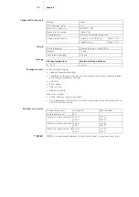
Page 24: ...In the ventricle bipolar Application Fixation in the right ventricle ventricular sensing pacing and defibrillation Shock coil RV Connections 1 x IS 1 1 x DF 1 Diameter 2 6 mm 7 8 F Insulation Silicone...

Page 25: ...m2 Material Platinum iridium alloy Surface structure Iridium fractal Distance to the lead tip 11 mm Length 50 mm Diameter 2 6 mm Area 290 mm2 Material Platinum iridium alloy Distance to the lead tip 1...

Page 26: ...a registered trademark for a particular cobalt chromium nickel alloy Design Cable DFT wires per cable 7 x 7 Material of conductor MP35N DFT Material of insulation Teflon PFA Outer diameter 0 28 mm inc...

Page 27: ...vents will not occur Lead malfunctions or failures Defense reactions of the body against lead implantation Medical complications including myocardial perforation during lead implantation or as a conse...

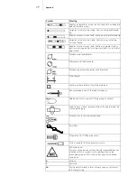
Page 28: ...packaging is damaged CE mark Unipolar IS 1 connector Bipolar IS 1 connector Unipolar DF 1 connector DF4 connector for ICD leads with one shock coil DF4 connector for ICD leads with two shock coils IS...

Page 29: ...ssible guide wire diameter Total length Surface and material of the indicated lead Recommended size of the lead introducer Additional stylets as part of the package contents Lead fixation sleeve premo...

Page 30: ...ppendix LV Positioning the lead in the coronary venous system for left ventricular pacing CS Coronary sinus Pace Pacing Sense Sensing Shock Shock DXA Dexamethasone acetate as steroid eluant Symbol Mea...

Reviews: