

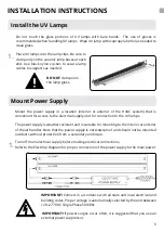
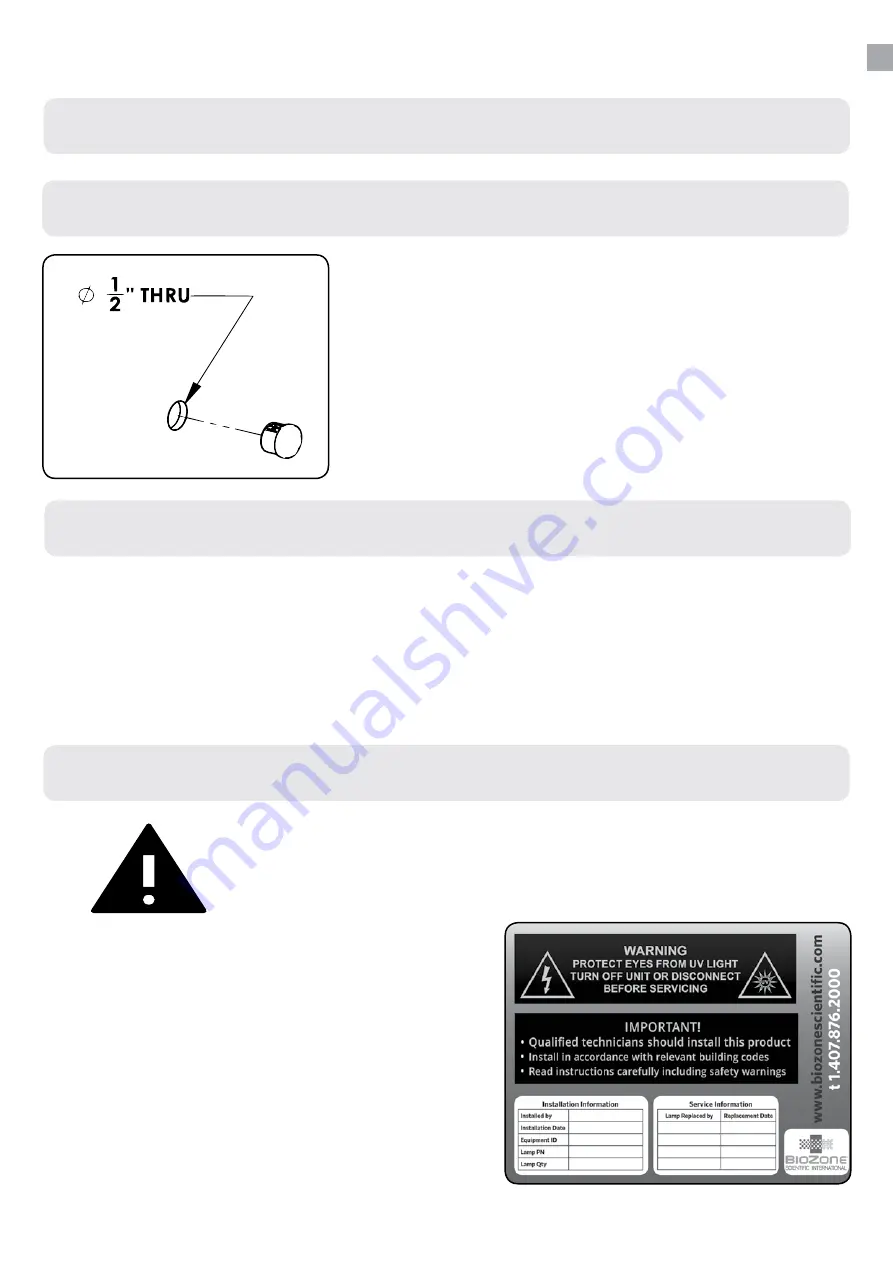
1.
Affix the UV Warning Label, shown here, to
the door or access panel used to service the
unit.
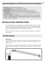
Safety Components
Install Sight Glass
Install an Optional Light Switch
1.
To help prevent accidental exposure to UV light, Biozone can provide an optional
on/off switch, to be installed by a licensed contractor on the circuit between the
main power supply and the CoilCare power supply. Electrical wire for the switch
not provided.
Contact BioZone for additional information.
2.
Record the installation information on
the UV Warning Label. The UV Warning
Label contains fields convenient to record
installation and service information. It is
recommended to record installation and
service details on the UV Warning Label as
those functions are performed.
INSTALLATION INSTRUCTIONS
8
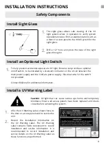
Install a UV Warning Label
Caution: UV light that can cause serious eye burns and temporary
blindness. Ensure all access panels have been replaced and doors
closed before activating the system.
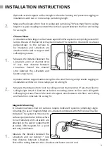
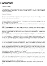
1.
The sight glass allows safe viewing of the UV
light system when in operation to verify system
operational status. Find a suitable location such as
a door or access panel to the HVAC system for the
sight glass.
2.
Drill a 1/2” hole and press the base of the sight
glass through it.


