II
Initialisation
Mechanical fine tuning
Electrical connections
C
o
n
n
e
c
ti
n
g
In
it
ia
li
sa
ti
o
n
III
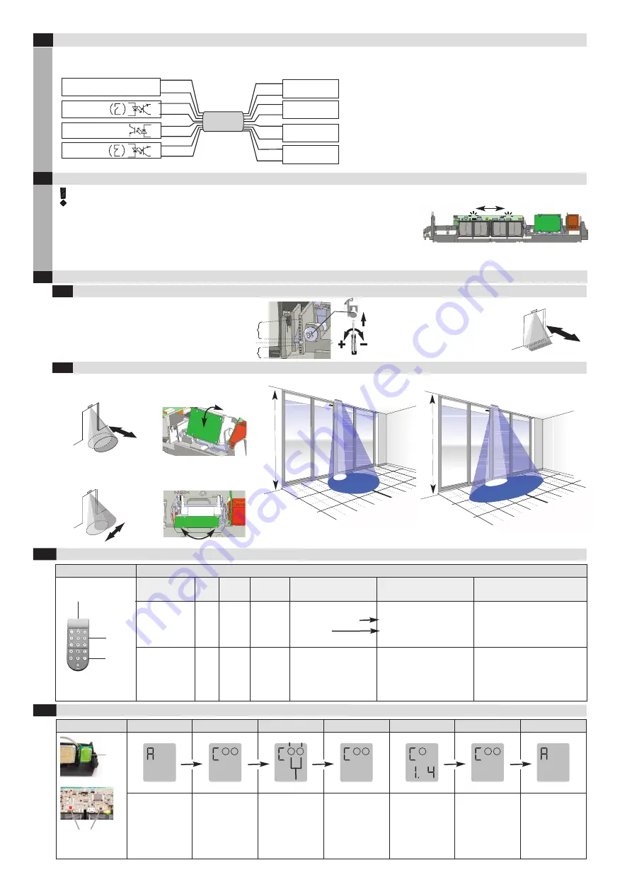
Once the detector has been connected to the power supply, it can be configured via the
Reglobeam within the next 30 minutes. Following initialisation, the red/green LED only lights up
when a detection has occurred.
The door system has been taken into operation at this point.
If any further settings or calibrations are required, proceed as described in the following section.
Remove the current supply all objects that do not form part of the usual door system environment from the door area BEFORE switching on.
Make sure that no-one is in the door area, otherwise correct startup will not be possible.
3
5
4
The alternate flashing shows the initialisation «teaching» of the detector. (Duration 20 - 25 sec.)
6
Configuration with Reglobeam remote control (refer to Reglobeam operating instructions)
Remote control:
Basic functions of the remote control:
IR interface
Function
Start
key
Functio
n key(s)
Number
key(s)
Display on
remote control
Function of the
remote control
Notes
Establishing
the connection
none
none
Continuously lit
flashes
Connection to the detector
No connection to the
detector
If
flashes, hold the remote
control closer to the detector and
point it more directly at the
detector, also check the batteries.
Establishing
the connection
with address
selection
none
–
It is
not
possible
to access
by Re-
globeam.
and the number of
the selected number
key
Address = Number of
the selected
number key
If
flashes, no connection,
If
and all numbers light up,
no configuration mode is acti-
vated.
PrimeTec / PrimeScan
Controller
white
brown
green
yellow
grey
pink
blue
red
Cable
white
brown
green
yellow
grey
pink
blue
red
Power Supply
–
+
RAD output
–
+
Test
–
+
AIR output
–
+
–
+
11.5 - 32 VDC
GND
+ In
GND
+ In
GND
+ In
PrimeTec A ES / PrimeScan A *
Controller
1 white
2 brown
3 green
4 yellow
5 grey
6 rose
7 blue
8 red
Cable
white
brown
green
yellow
grey
rose
blue
red
Power Supply
–
+
Radar output
–
+
Test
–
+
AIR output
–
+
–
+
11.5 - 32 VDC
3 m
–
+
–
+
–
+
Radar IN
Test
AIR IN
Number
keys
Function
keys
7
Configuration by hand (Operator buttons)
1m
2m
3m
1m
2m
0m
0m
1m
2m
2.
2
m
1m
2m
3m
1m
2m
0m
0m
1m
2m
2.
2
m
red LED
green LED
*) Value is going to be saved by switching to other parameters
* For other versions (eg. PrimeTec A ES.SM.V) see supplementary sheet
–
+
5.1
5.2
Radar field (PrimeTec)
AIR-field (PrimeTec / PrimeScan)
–
–
+
+
–
–
+
+
Manual settings of the inclination
0° ... +90° in 5° steps
Settings of the inclination angle on the
adjustment screw:
Inclination: -5° – +7° continuously
adjustable
Manual settings of the pivoting
-20° ... +20° in 5° steps
–
–
+
+
+
–
Round radar field
Wide radar field
min. = 0.5 x 0.5m (WxD)
max. = 2.7 x 1.9m (WxD)
min. = 1.1 x 0.6m (WxD)
max. = 4.7 x 1.7m (WxD)
0°
+ 1 … + 7°
– 1 … – 5°
Automatic
Config. mode
Choose
Choose
Funct./Parameter Back to choice Back to autom.
1
2
1
2
1
2
1
1
2
Detector in
automatic mode
Press both
buttons
simultaneously
Red button:
switch
Black button:
choose
Red button:
Choose
parameter *
Black button:
Choose value of
the parameter
Press both
buttons
Press both
buttons
Operator buttons
red
(Mode) &
black
(Data)
General
LCD
Radar AIR
➝
see table parameter 3
➝
see table parameter 3


