Measure Match Mode
37
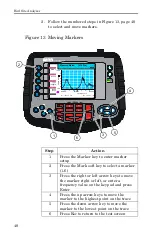
You can activate and use up to six markers to visually
indicate the trace value at specific frequency points.
All markers follow the current trace only. The site
analyzer displays the frequency and signal value for
each marker at the bottom of the screen. You can
display each marker as a triangle pointer or a vertical
line through the trace. You can also display the
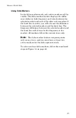
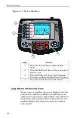
difference (delta) in frequency between two markers.
Markers indicate VSWR to 0.01, and Return Loss or
Cable Loss to 0.1 dB.
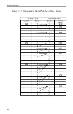
When you display both a recalled trace and the current
measurement trace at the same time, there is an addi-
tional marker option, single mode and dual mode. In
single mode, the markers function normally (indicat-
ing the frequency and value at the marker). In dual
marker mode, you select a marker using the Mark soft
key and, at the bottom of the screen, the site analyzer
displays the marker number, the frequency and value
of the current trace at the marker, and the difference
in frequency and value between the current trace and
the recalled trace. The difference in frequency is
always 0.00 (zero). Only the first three markers (M1,
M2, M3) are available in dual mode.
Activate Markers and Set Marker Style
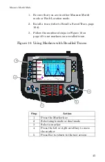
1. Be sure that you are in either Measure Match
mode or Fault Location mode.
2. Follow the numbered steps in Figure 12, page 38
to activate markers and set their style.
Summary of Contents for SITE ANALYZER SA-1700EX
Page 2: ...This page is not blank...
Page 8: ...Bird Site Analyzer vi...
Page 9: ...vii...
Page 30: ...Bird Site Analyzer 16...
Page 142: ...Bird Site Analyzer 128...
Page 148: ...Bird Site Analyzer 134...
Page 159: ...Maintenance 145 Measured Return Loss dB...
Page 167: ...Maintenance 153 the number of data points you wish measure 238 475 949...


