background image

50

Chapter 7

Maintenance

Cleaning

Clean the SiteHawk Analyzer only with a soft cloth dampened with mild 
detergent and water. Do not use any other type of cleaning solution.

CAUTION

Do not touch the center pin of the Antenna Test Port with bare hands, water, 

or emery cloth. Otherwise, damage may occur to the connectors surface.

Clean the connector using a cotton swab dipped into an isopropyl 
alcohol solution. 

Ensure connectors are completely dry before making cable 
connections.

Charging the Battery

The internal battery pack will automatically recharge when the SiteHawk 
Analyzer is connected to the AC adapter.

Recharging time, from a full discharge, is approximately 5 hours with the unit 
powered off.

CAUTION

Only use the supplied AC adapter to charge the unit. 

The unit cannot be charged through a USB port (i.e. from a laptop). 

Charging from a power source other than the supplied charger may damage 

the battery.

Summary of Contents for SiteHawk SK-6000

Page 1: ...SiteHawk Analyzer SK 6000 Operation Manual Copyright 2019 by Bird Technologies Inc Instruction Book Part Number 920 SK 6000 Rev B SiteHawk is a trademark of Bird Electronic Corporation ...

Page 2: ... to remove the RF transmission line while RF power is present WARNING Do Not Service Or Adjust Alone Under no circumstances should any person reach into an enclosure for the purpose of service or adjustment of equipment except in the presence of someone who is capable of rendering aid WARNING Safety Earth Ground An uninterruptible earth safety ground must be supplied from the main power source to ...

Page 3: ...nt cautions appear in the text and are repeated here for emphasis CAUTION Do not connect the unit to a PC USB port File transfer must be done using a USB Drive See Page 39 45 and 56 CAUTION Only use the supplied AC adapter to charge the unit The unit cannot be charged through a USB port i e from a laptop Charging from a power source other than the supplied charger may damage the battery See pages ...

Page 4: ...ÓN DE SEGURIDAD DEL INSTRUMENTO BENUTZUNG WIRD DAS GERÄT AUF ANDERE WEISE VERWENDET ALS VOM HERSTELLER BESCHRIEBEN KANN DIE GERÄTESICHERHEIT BEEINTRÄCHTIGT WERDEN UTILISATION TOUTE UTILISATION DE CET INSTRUMENT QUI N EST PAS EXPLICITEMENT PRÉVUE PAR LE FABRICANT PEUT ENDOMMAGER LE DISPOSITIF DE PROTECTION DE L INSTRUMENT IMPIEGO QUALORA QUESTO STRUMENTO VENISSE UTILIZZATO IN MODO DIVERSO DA COME S...

Page 5: ...GERÄTES GELTEN NUR FÜR GESCHULTES FACHPERSONAL ZUR VERMEIDUNG GEFÄHRLICHE ELEKTRISCHE SCHOCKS SIND WARTUNGSARBEITEN AUSSCHLIEßLICH VON QUALIFIZIERTEM SERVICEPERSONAL DURCHZUFÜHREN ENTRENTIEN L EMPLOI DES INSTRUCTIONS D ENTRETIEN DOIT ÊTRE RÉSERVÉ AU PERSONNEL FORMÉ AUX OPÉRATIONS D ENTRETIEN POUR PRÉVENIR UN CHOC ÉLECTRIQUE DANGEREUX NE PAS EFFECTUER D ENTRETIEN SI L ON N A PAS ÉTÉ QUALIFIÉ POUR C...

Page 6: ...ICIO AUTORIZADO PUEDE REEMPLAZARLAS GERÄTE SIND MIT WIEDER AUFLADBAREN BATTERIEN BESTÜCKT BATTERIEN SIND NUR VON QUALIFIZIERTEM SERICE PERSONAL AUSZUWECHSELN CES DISPOSITIFS SONT ÉQUIPÉS DE BATTERIES RECHARGEABLES SEUL LE PERSONNEL D ENTRETIEN AUTORISÉ EST HABILITÉ À LES REMPLACER LE UNITÀ SONO DOTATE DI BATTERIE RICARICABILI CHE DEVONO DA COME SPECIFICATO DAL PRODUTTORE LA PROTEZIONE DI SICUREZZA...

Page 7: ...roduction Describes the features of the Bird SiteHawk lists equipment supplied and optional equipment provides power up instructions and measurement settings Measure Match Mode Lists the steps to make match measurements as well as providing instructions for all functions available in Measure Match mode Fault Location Mode The DTF measurement shows the location of any problems in the antenna system...

Page 8: ... 4 RF Cable 1 Meter Specifications 4 Measurement Capability 5 Controls Indicators Connectors and Ports 5 Power 6 Powering On 6 Powering Off 6 Sleep Mode 6 Measurement Port 7 User Interface 7 Setting the Measurement Frequencies 9 Changing Measurement Frequency on the Display 9 Changing Measurement Frequency on the FREQ Menu 9 Setting the Measurement Data Points 10 Changing the Number of Measurement...

Page 9: ...rming a Cable Loss Measurement 18 Interpreting a Cable Loss Measurement 19 Chapter 4 Fault Location Mode 20 Frequency Span and Max Distance 20 Max Distance 20 Data Points 21 Frequency Span 21 Velocity of Propagation 21 Calculating the Frequency Span 21 Selecting Fault Location Mode 22 Interpreting the Fault Location Measurement 24 Chapter 5 Additional Features 25 Limit Line 25 Setting Limit Lines ...

Page 10: ...ta 42 Deleting SiteHawk Stored Data Files 43 Data Transfer Function 45 SiteHawk Communications Settings 49 Accessing Communication Services 49 Chapter 7 Maintenance 50 Cleaning 50 Charging the Battery 50 Replacing the Battery 51 Device Calibration 51 Storage 51 Edit Cable List 52 Edit Cable List on SiteHawk 52 Edit Cable List on a PC 54 Firmware Update 56 Customer Service 57 Limited Warranty 59 ...

Page 11: ...a points measured across a user specified frequency band or distance range are graphed on a 1280 x 720 pixel touch screen display area Power Meter Application SiteHawk Analyzers include the Bird RF Meter Application The Bird RF Meter is an Android application designed to work with a wide variety of Bird Power Sensors To measure transmitter power connect an external power sensor to the SiteHawk Pow...

Page 12: ...Carrying Case 7002A219 1 USB Adapter SK CONN OTG 2 AC Adapter 12 VDC SK05T 1200300Z Touch Pen stylus SK TP 112 USB Drive 5A2745 1 Instruction Manual 920 SK 6000 RF Cable 1 meter SK TC MNFN 1M Calibration Combination Cal Combo DC 6 GHz SK CAL MN C6 Li ion Battery 7 4 V 6800 mAh SK BTY 7468 N type Male to 7 16 DIN Female adapter PA MNFE ...

Page 13: ...B F 0 02 dB C Return Loss Measurement Range Resolution 0 dB to 60 dB 0 01 dB VSWR Measurement Range Resolution 1 0 to 65 0 0 01 Cable Loss Measurement Range Resolution 0 dB to 30 dB 0 01 dB DTF Range 0 to 5000 ft 0 to 1500 m Test Port Connector Impedance N type Female 50 ohms Connector USB C USB 3 0 Dimensions L W H 7 7 x 3 6 x 2 4 in 195 x 90 x 60 mm Weight 1 98 lbs 0 9 kg Maximum Input Power 22 ...

Page 14: ...nterfering Signals 13 dBm CE CE compliant EMC Safety and RoHS Battery 10 hours continuous use 7 4 V 6800 mAh Battery Charge Time Power Off Power On 5 Hrs for full charge 8 Hrs for full charge Languages English Chinese Spanish Frequency DC 6 0 GHz Resistance 50 Ohm Average Power 1 W Connectors Load Return Loss VSWR 35 dB 1 032 Open Phase Deviation 0 6 Short Phase Deviation 0 6 Operating Temperature...

Page 15: ...to temporarily store a trace Frequency Start Stop or Center Span frequencies Return Loss dB Cable Loss dB SWR ratio DTF SWR ratio or DTF Return Loss dB Controls Indicators Connectors and Ports Figure 1 SK 6000 Controls Indicators Connectors and Ports 1 Antenna Test Port Female N connector for connecting to the antenna Use a phase stable cable for best results 2 Power Button Used to power on and of...

Page 16: ... from a full discharge is approximately 5 hours with unit powered off Note When the unit is received the battery may not be fully charged An AC adapter should be used when operating the unit for the first time Powering On 1 Press Power button for 5 seconds Note Unit will complete power up in approximately 30 secs Powering Off 1 Press Power button for three seconds Note A Device Options dialog will...

Page 17: ...wk to the system The measurement port is a 50 ohm N type This port is used to connect the device under test User Interface The SiteHawk user interface consists of a touch screen interface The user presses the screen to access menus change settings perform measurements and save results Note The displays used in this manual are shown with the SiteHawk in the horizontal position some menus may displa...

Page 18: ... visual indicator 13 Stop Frequency press the data field to change the value or press the label to change to frequency Span 17 14 Sweep display area 15 Points press the data field to choose the number of measurement points 16 Start Frequency press the data field to change the value or press the label to change to Center Frequency 18 17 Span displays the current frequency span Press the data field ...

Page 19: ...minimum or maximum frequency of the model There are two methods available to change the start stop center frequencies and frequency span display screen entry and FREQ menu entry Changing Measurement Frequency on the Display 1 Press the data field of the frequency to change 2 Type the new value using the number pad 3 Press Enter Changing Measurement Frequency on the FREQ Menu 1 Press the Menu icon ...

Page 20: ...detail in Measure Match mode measurements When saving a trace the number of data points collected are saved A progress bar just below the x axis will indicate the progress of the sweep When the number of measurement data points are changed the current trace is erased and the Save softkey is disabled until the sweep finishes and the screen displays the first new trace Changing the Number of Measure...

Page 21: ...units settings Note The system default unit m optional unit ft Start Distance 1 Select the input box 2 Set start distance Stop Distance 1 Select the input box 2 Set stop distance Windowing Windowing is an option on the SK 6000 that will digitally average the data on the displayed trace in effect making the trace appear smoother In some situations it will make individual problems easier to spot but...

Page 22: ...t be entered in dB ft or dB meter The manufacturer generally gives these values as dB 100ft or dB 100meters Cable List The Cable List contains known cable values for a variety of cable types The Cable List may be edited to add or delete cables See Edit Cable List on page 52 1 Select CableList 2 Set cable type 3 Select a certain cable type Note Each cable type in the cable list has the fixed values...

Page 23: ...ted to indicate the active Trace 2 Trace Count Setting a Press the Trace icon on the menu bar b Choose the number of traces to display x1 x2 or x4 Note Every trace has a name Tr1 Tr2 Tr3 or Tr4 the name cannot be changed 3 Change one or both trace limits to change the grid scale for the trace Set the maximum value a Press the maximum value to open the Top value dialog b Enter a maximum value Set t...

Page 24: ...e Figure 6 on page 14 2 Select one of the following from the menu a For Manual Operation Press Top to change upper limit of the display Press Bottom to change the lower limit of the display b For Auto Scale Press Auto Scale for the system to choose the best fit for the active trace Note The scale can also be dynamically changed by pressing and dragging the trace up or down in the display window Fi...

Page 25: ...calibrating the unit 1 Press the Calibrate icon 2 Connect the Cal Combo Open connector to the unit antenna port 3 Press the Open softkey 4 Wait for the unit to sweep and a Green Check to display 5 Connect the Cal Combo Short connector to the unit antenna port 6 Press the Short softkey 7 Wait for the unit to sweep and a Green Check to display 8 Connect the Cal Combo Load connector to the unit anten...

Page 26: ...ess trace measurement field to display menu 2 Select one of the following from the Measurement Mode menu ReturnLoss SWR Note When making a match measurement select units for the Y vertical scale SWR for standing wave ratio or Return Loss for dB Figure 8 Selecting the Measure Match Mode 3 Select the number of Data Measurement points 4 Set the Frequency range Note Frequency range should be greater t...

Page 27: ...ion off Always set the frequency before calibrating the unit 6 Connect the SiteHawk to the device under test 7 Wait 10 Seconds for the sweep to update Interpreting the Measurement The graph below shows a typical Match Measurement on an antenna Figure 9 Interpreting Match Measurement The graph contains the following elements Vertical grid scale y axis displays dB and ratio data values Horizontal gr...

Page 28: ...set the start frequency at 400 and the stop frequency at 500 MHz For an 800 MHz antenna set the start frequency at 700 and the stop frequency at 1 100 MHz 4 Connect a phase stable cable to the SiteHawk Analyzer antenna test port 5 Calibrate the SiteHawk Analyzer See Calibration on page 15 Note After Calibration with the load still connected the Output must be below 25 dB If not there may be an iss...

Page 29: ...t Note that the scale is greatly reduced to show the cable s variation across frequency Figure 11 Interpreting Cable Loss Measurement 1 Marker 1 and Marker 2 indicate the minimum and maximum loss for the cable under test 2 Take the average of M1 and M2 Note This is the average cable loss across the frequency band 3 Compare the loss with the manufacturer s specified loss for a cable of this length ...

Page 30: ...f the cable Vp and the number of measured data points determine the maximum distance tested during fault location test Max Distance The maximum measurable distance can be calculated by SiteHawk based on the specified frequency span or the maximum distance can be entered manually instead of entering the frequency span If the maximum distance being measured is entered instead of the frequency span t...

Page 31: ...stance Narrowing the frequency span increases the measurable distance Velocity of Propagation The velocity of propagation Vp is a characteristic of the cable and is expressed as a percentage Consult the cable manufacturer s specifications to get the velocity of propagation value for the cable being used Calculating the Frequency Span T 1 F N 1 Fmax Fmin DTFmax C V p T 2 C V p N 1 2 Fmax Fmin Note ...

Page 32: ... start and Stop frequencies 5 Press Start distance field and enter the start value 6 Press the Stop distance field and enter the stop value 7 Press DTF Menu 8 Press Window selection to change the display to the desired value 9 Enter Cable data using one of the following methods a Press velocity and enter the cable velocity Press cable loss and enter the cable loss value b Press cable list select t...

Page 33: ...mended a load or attenuator be used to bleed off any static charge prior to connecting the SiteHawk to the system 12 Connect the SiteHawk Analyzer to the cable being tested Note If the SiteHawk Analyzer is calibrated with a phase stable cable connected to its antenna port do not remove the cable Connect it to the cable to be tested 13 Wait at least 10 seconds for the sweep to update 14 Press the M...

Page 34: ...kes where there are no components represent faults Note the distance and check the line at that point for damage The largest spike is usually due to the antenna Typically the trace after the antenna can be ignored Note If a maximum distance less than the total length of the cable system is selected the trace will not show the end of the cable system antenna To display the full cable system always ...

Page 35: ...de acceptable limits can be visually and audibly enhanced using a failure flag and alarm Note Limit lines are available in any measurement mode Setting Limit Lines 1 Press LIMIT icon Figure 14 Limit Menu 2 Select from the following limit options Limit On Off Press to toggle limit line on and off Style Max Min Press to toggle maximum or minimum limit line Note When the Style is set to Max anything ...

Page 36: ...limit line the value in the Step field Move Down Press to move limit line down the vertical scale Each press will move the limit line the value in the Step field FailFlag On Off Press to toggle fail flag on and off The words PASS or FAIL will be displayed in the sweep display area to indicate if the active signal is within or outside the limits set by the limit line FailAlarm On Off Press to toggl...

Page 37: ...ers can also be displayed Markers indicate SWR to 0 01 and Return Loss or Cable Loss to 0 1 dB Setting Markers 1 Press the MKR icon Figure 16 Marker Menu 2 Select from the following marker options Add Press Add to add a marker Delete Pressing Delete will the active marker If deleting a marker select the marker before opening the marker menu Freq Indicates the current frequency position of the acti...

Page 38: ...o the right Each press will move the active marker the value in the Step field Search Max Press to move the active marker to the maximum value position on the trace Search Min Press to move the active marker to the minimum value position on the trace DeltaMarker Press to toggle delta marker function on and off MoveDelta Press to move the delta marker indicator to highlight a specific delta marker ...

Page 39: ...ast two markers must be displayed for the Delta Option to work 1 Select the marker on the screen to be the active marker Note In Figure 18 marker 3 is the active marker marker 1 and 2 are turned on Figure 18 Active Marker 2 Press MKR icon and select DeltaMarker Note In Figure 19 marker 3 is highlighted markers 1 and 2 are now delta markers 1 3 and 2 3 Delta markers 1 3 and 2 3 display values that ...

Page 40: ...Additional Features 30 3 Press MKR icon and select MoveDelta Note Figure 20 shows Marker 1 3 is now highlighted Figure 20 Highlighted Delta Marker ...

Page 41: ...t be displayed for the peak search between markers to work Marker 3 will always find the peak between marker 1 and 2 regardless of how many other markers are displayed and marker 6 will always find the peak between marker 4 and 5 1 Press MKR icon and Add markers 1 2 and 3 If desired add markers 4 5 and 6 also 2 Move marker 1 and 2 to the upper and lower limit for the peak search If desired move ma...

Page 42: ... icon will display the utility menus MEM FREQ RESET FILE PNG SYS See Figure 22 These menus are described in this section with the exception of the FREQ menu the FREQ menu is described in Setting the Measurement Frequencies on page 9 Figure 22 Utility Menus ...

Page 43: ...eenshots Screenshots can be saved by using the Save Screen Picture options on the File menu or by pressing the PNG Icon The current time is added to all screen shots The site name may be added as an option Save Screen Picture png Saves a PNG file of the current Sweep Display Area press the menu option and a save dialog is displayed allowing the user to enter a file name or use the default file nam...

Page 44: ...n Edit SiteName dialog box will be displayed each time screen shot is taken Color Screen Shot Press to toggle screen shots in color or black and white When set to OFF screen shots will be black and white when set to ON screen shots will be in color See Figure 24 Note The default setting for Color Screen Shot option is ON If the reset function is executed on the SK 6000 the Color Screen Shot option...

Page 45: ... will be included on all screen shots After Site Name is set to ON an Edit SiteName dialog box will be displayed each time a screen shot is taken See Figure 26 The site name must be entered the first time a screen shot is saved Note The default setting for the Site Name option is OFF If the reset function is executed on the SK 6000 the Site Name option is reset to OFF Figure 26 Site Name Dialog Bo...

Page 46: ...ttings All current data is cleared including calibration and all menus are reset to default Saved data is not affected by a reset 1 Press the Menu icon 2 Press RESET A Reset dialog will open click OK to confirm reset PNG Icon Pressing PNG will save the current sweep display area as an image with a PNG file type extension The save path and filename will briefly be displayed at the bottom of the scr...

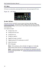
Page 47: ...u is best viewed with the SiteHawk in the vertical position User options include Change Trace color Change limit Line color Change font size Change line widths Toggle Full Screen on and off Toggle display of GPS coordinates on and off Adjust the volume Select Language Note GPS coordinates when selected will appear on the display along with the date and time see User Interface on page 7 Note Locati...

Page 48: ...XIT Press the exit icon on the SYS menu to close the SiteHawk application About Screen Press the information icon on the SYS menu opens the About Screen The About screen displays the software version and the device serial number Figure 32 System About ...

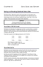
Page 49: ...s The current format and response trajectory under the incentive value is stored in the CSV file Trace data is saved in the following format to the CSV file F n Frequency about point N Data1 Trace response value Real part Data2 0 Imaginary part Trace Data S1p File SiteHawk can save the parameters to the S1p file The S1p file contains the frequency value and S parameter S1p files are used to store ...

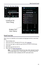
Page 50: ... dB and Phase Z0 reference impedance F n Frequency about point N RI MA DB RI MA DB Save Files on SiteHawk The SiteHawk Analyzer automatically names files using a time date format this can be changed during the save operation Figure 33 SiteHawk File Names Saving Files 1 Press the Menu icon 2 Press the FILE icon to display the file menu See Figure 34 ...

Page 51: ...ave Multiple Files select multiple file types to save as a group 4 Press appropriate Save icon each save type has its own save button Note Unless a custom name is entered a default filename will be automatically generated This file will be saved to the internal memory of the unit 5 Change the file name if desired See Figure 35 on page 42 6 If Save Multiple Files was selected select checkboxes for ...

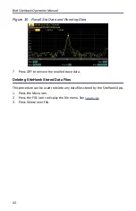
Page 52: ...con to display the file menu See Figure 34 3 Press the Save Type to select file type STATUS CAL cst or STATUS sta 4 Press Load 5 Select the data file from the list 6 Press Load See Figure 36 page 43 Note The active and the recalled trace data will be displayed together in the sweep display area In the example Tr1 is the active trace the recalled trace data is indicated with OFF and the file name ...

Page 53: ...Data 7 Press OFF to remove the recalled trace data Deleting SiteHawk Stored Data Files This procedure can be used to delete any data files stored by the SiteHawk App 1 Press the Menu icon 2 Press the FILE icon to display the file menu See Figure 34 3 Press Delete User File ...

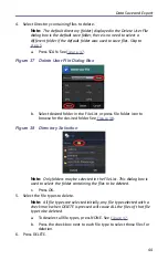
Page 54: ...r press file folder icon to browse for the desired folder See Figure 38 Figure 38 Directory Selection Note Only folders may be selected in the File List This dialog box is used to select the folder containing the files to be deleted c Press OK 5 Select the file types to delete Note All file types are selected initially any file type selected with a check mark when DELETE is pressed will cause ALL ...

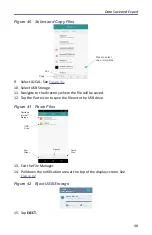
Page 55: ...mory with the use of an external USB drive and the USB adapter supplied CAUTION Do not connect the unit to a PC USB port File transfer must be done using a USB Drive 1 Connect the USB drive to the USB adapter then connect the USB adapter to the USB C port at the bottom of the unit 2 Press Home key on the SiteHawk display 3 Select the Files icon on the unit s home screen 4 Select LOCAL See Figure 3...

Page 56: ...USB Storage 11 Navigate to the directory where the file will be saved 12 Tap the Paste icon to save the file onto the USB drive Figure 41 Paste Files 13 Exit the File Manager 14 Pull down the notification area at the top of the display screen See Figure 42 Figure 42 Eject USB Storage 15 Tap EJECT ...

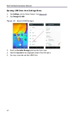
Page 57: ... from Settings Menu 1 Tap Settings on the Home Screen See Figure 43 2 Tap Storage USB Figure 43 Eject USB Storage 3 Scroll to Portable Storage and tap the Eject icon 4 Wait for Ejected to be displayed under the USB name 5 You may now remove the USB Drive ...

Page 58: ...orage SiteHawk storage Local in the File Manager program 7 Navigate to the location of the file Figure 44 File Selection 8 Select the file to be copied See Figure 44 9 Tap the options menu 10 Tap Share 11 Select Bluetooth option for sharing 12 Scan for available devices Note You may need to make the destination device visible to other devices in it s setting s menu 13 Select the destination device...

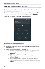
Page 59: ...Accessing Communication Services 1 Swipe your finger down from the top of the display screen to access the notification area 2 Tap the service Icon to start or stop the service a Location tapping location icon turns location services off or on A slash through the icon indicates the service is OFF as shown in Figure 45 b WiFi tapping WiFi icon turns WiFi off or on Tap the dropdown below the icon to...

Page 60: ...cotton swab dipped into an isopropyl alcohol solution Ensure connectors are completely dry before making cable connections Charging the Battery The internal battery pack will automatically recharge when the SiteHawk Analyzer is connected to the AC adapter Recharging time from a full discharge is approximately 5 hours with the unit powered off CAUTION Only use the supplied AC adapter to charge the ...

Page 61: ...ttery access cover and two screws to secure cover 5 Charge the battery Device Calibration It is recommended that an instrument calibration be performed by a certified service provider at nominal three year intervals Contact Bird Electronic for more information Storage Store the SiteHawk Analyzer in an enclosed case and in an environment that does not exceed values listed in the Specifications sect...

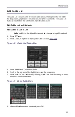
Page 62: ...d Cable to Cable List Note cables in the default list cannot be changed using this method 1 Press DTF icon 2 Press CableList option to display the Cable List See Figure 48 Figure 48 Cable List Dialog Box 3 Press Add button to add new cable 4 Scroll to the bottom of the Cable List to see the new entry 5 Press each cell for Cable name Velocity Cable Loss and Frequency to enter the new cables informa...

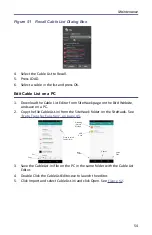
Page 63: ...5 Press Delete button to delete cable Save Cable List 1 Press DTF icon 2 Press CableList option to display the Cable List See Figure 48 3 Press Save Figure 50 Save Cable List Dialog Box 4 Press File Name to give the Cable List a unique filename 5 Press SAVE to save the Cable List Recall Cable List Note This procedure is used to load a Cable List different from the Cable List currently displayed 1 ...

Page 64: ...ist Editor from SiteHawk page on the Bird Website and save on a PC 2 Copy the file CableList ini from the SiteHawk folder on the SiteHawk See Data Transfer Function on page 45 3 Save the CableList ini file on the PC in the same folder with the Cable List Editor 4 Double Click the CableListEditor exe to launch the editor 5 Click Import and select CableList ini and click Open See Figure 52 ...

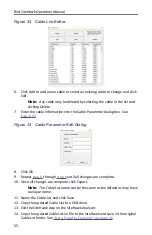
Page 65: ...3 Figure 53 Cable Parameter Edit Dialog 8 Click OK 9 Repeat step 6 through step 8 until all changes are complete 10 Once all changes are complete click Export Note The Cable List name can be the same as the default or may have a unique name 11 Name the Cable List and click Save 12 Copy the updated Cable List to a USB drive 13 Exit the SiteHawk App on the SiteHawk Analyzer 14 Copy the updated Cable...

Page 66: ... link Note Ensure you are downloading the firmware for correct SiteHawk model 4 Download the SiteHawk Firmware XXX apk update file 5 Connect the USB drive to the PC CAUTION Do not connect the unit to a PC USB port File transfer must be done using a USB Drive 6 Transfer the SiteHawk Firmware XXX apk update file to the USB drive 7 Remove the USB drive 8 Connect the USB drive to the USB adapter See F...

Page 67: ...ocedure beyond the scope of those in this chapter should be referred to a qualified service center If the unit needs to be returned for any reason request an Return Material Authorization RMA through the Bird Technologies website All instruments returned must be shipped prepaid and to the attention of the RMA number Bird Service Center 30303 Aurora Road Cleveland Solon Ohio 44139 2794 Fax 440 248 ...

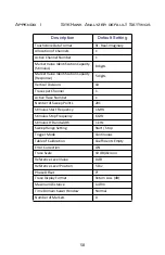
Page 68: ...ons 10 Traces per Channel 1 Active Trace Number 1 Number of Sweep Points 201 Stimulus Start Frequency 1 MHz Stimulus Stop Frequency 6 GHz Stimulus IF Bandwidth 1 kHz Sweep Range Setting Start Stop Trigger Mode Continuous Table of Calibration Coefficients Empty Error Correction ON Trace Scale 10 dB division Reference Level Value 0 dB Reference Level Position 5 Div Phase Offset 0 Trace Display Forma...

Page 69: ...very such claim for breach of these war ranties shall be deemed to be waived by Buyer unless made in writing within ten days from the date of discovery of the defect The above warranties shall not extend to any products or parts thereof which have been subjected to any misuse or neglect damaged by accident rendered defective by reason of improper installation or by the performance of repairs or al...

Reviews: